
Install Manual

Gaseous Fuel Systems
26 Installation Guidelines For Spark-Ignited Stationary Generators
Final Operating Test
A correctly configured and sized fuel system provides the
fuel volume and fuel pressure required for the generator
set to operate correctly in all modes of operation. To ver
-
ify correct fuel system operation, a series of tests must
be performed as described below.
Fuel Shutoff Valve
Most applications will require an external manual fuel
shutoff valve on the fuel line. The fuel shutoff valve must
be readily accessible. Local codes determine correct
location.
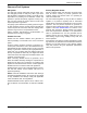
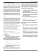
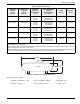
Figure 4-4. Fuel Shutoff Valve with Manometer Port
NOTE: Figure 4-4 illustrates a fuel shutoff valve with a
manometer port for making fuel pressure checks. This
accessory fuel shutoff valve permits making pressure
checks without going into the generator enclosure.
Valves available through Generac and IASD’s:
• 3/4 in pressure rated ball valve, part number 0K8754
• 1 in pressure rated ball valve; part number 0K8184
• 1-1/4 in pressure rated ball valve; part number
0L2844
• 1-1/2 in ball valve; part number 0L2856
• 2 in ball valve; part number 0L2846
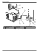
Fuel Pressure Test Port Location
Using a suitable pressure gauge or water manometer,
measure fuel pressure to the generator at a test port
located before the fuel solenoid shutoff valve(s).
See A of Figure 4-5. On units using demand type fuel
regulator(s), there may be a factory-installed 1/8 in pipe
port in a tee fitting connected to the low pressure switch.
See B of Figure 4-5. If unit has a low pressure switch
without the tee, install a tee and plug it between the low
pressure switch and the test port on the fuel regulator
body using a suitable pipe dope. Use only the upper port
on fuel regulator body, as it detects supply fuel pressure
even when the unit solenoid valve is closed. This allows
static fuel pressure to be measured, as well as fuel pres
-
sure when cranking, while running at no load, and while
running at full load.
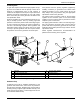
See C of Figure 4-5. Factory installed at the test point,
some units may be provided with a special test port plug
known as a “Pete’s Plug
®
.” The plug allows fuel pressure
test readings to be taken quickly without leaving costly
gauges installed in the fuel line.
Use the “Pete’s Plug” as follows:
1. Clean and lubricate gauge adapter probe with a
small amount of petroleum jelly or silicone grease.
2. Assemble gauge adapter.
3. Screw barbed fitting into gauge adapter using the
appropriate sealant.
4. Install fuel line of correct pressure gauge onto
barbed fitting.
5. Slowly unscrew protective cap from test port plug.
NOTE: Quickly tighten cap if escaping gas or liquid is
heard or felt. Replace plug if faulty.
6. Insert gauge adapter into test port plug and secure.
7. Remove gauge adapter probe and screw protec-
tive cap onto fuel pressure test port plug once fuel
pressure reading is obtained.
NOTE: Take necessary readings as quickly as possible.
Severe deformation of valves may occur if gauge adapter
probe is left in test port plug for a period of hours or days.
NOTE: Below 45 °F (7 °C), the neoprene core of the plug
does not recover its original shape as rapidly as it would
at higher temperatures. Upon removal of gauge adapter
probe, valves may not close fully and immediately, or
they may remain slightly open until operating tempera-
ture is above 45 °F (7 °C). Lower pressures and the
length of time gauge adapter probe is inserted can also
affect valve closing rate. The protective cap is provided to
eliminate the small amount of leakage that might occur
following removal of the gauge adapter probe.
8. Tighten protective cap to prevent tampering.
000743