
Install Manual
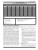
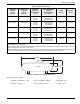

Table 4-2. LP Gas Pipe Sizing
LP Gas 11–14 in of Water Column (2.7
4–3.48 kPa)
Table values are maximum pipe run in ft (m)
kW 0.75 in
(1.9 cm)
1 in
(2.5 cm)
1.25 in
(3.2 cm)
1.5 in
(3.8 cm)
2 in
(5.1 cm)
2.5 in
(6.4 cm)
3 in
(7.7 cm)
RG 22 20 (5.1) 100 (30.45) 400 (121.9) — — — —
25 and 30 50 (12.7) 200 (50.8) 800 (243.8) — — — —
27 15 (4.6) 70 (21.4) 300 (91.4) 625 (190.5) — — —
32 10 (2.5) 60 (18.3) 280 (85.3) 550 (167.6) — — —
36 — 20 (5.1) 150 (45.7) 325 (99.1) 950 (289.6) — —
38 10 (2.5) 35 (10.7) 200 (60.9) 450 (137.2) — — —
45 — 10 (2.5) 80 (24.4) 200 (60.9) 600 (182.9) — —
48 — 10 (2.5) 80 (24.4) 200 (60.9) 600 (182.9) — —
60 — 10 (2.5) 40 (12.2) 100 (30.5) 350 (106.7) — —
Note: Size fuel pipe to the sizing charts or to local codes. When installing other than Sch. 40 black pipe, see manufacturer’s sizing charts.
The liquid-cooled generator is not a constant flow appliance. The
fuel pipe was sized large enough to supply at least 100% of the generator BTU/
hr rating.
LPG
• 8.55 ft
3
/lb (548.02 L/kg)
• 4.24 lbs/gal (0.51 kg/L)
• 2500 BTU/ft
3
(93.2 kJ/L)
• 36.3 ft
3
= 1 gal (0.272 m
3
/L)
Pressure
1 in water column = 0.25 kPa
11–14 in water column = 2.74–3.48 kPa
Note:
• Pipe sizing is based on 0.5 in water column (0.12 kPa) pressure drop.
• Sizing includes a nominal number of elbows and tees.
• Verify adequate service and meter sizing.
• Tables based on black pipe.
Gaseous Fuel Systems
Installation Guidelines For Spark-Ignited Stationary Generators 23
Sizing LP Tanks for LP Gas Withdrawal
The manufacturer recommends the installer contact a
reputable LP gas supplier when sizing LP gas storage
tanks and the associated pressure regulators and piping
systems. Many factors come into play when working with
LP in either its vapor or liquid form.
The operation of an LP gas system depends on vaporiza-
tion of liquid propane stored i
n the tanks. As vapor above
liquid propane level is withdrawn, pressure in LP gas tank
decreases. This change in pressure causes LP gas to
“boil” in order to restore pressure equilibrium. The liquid
propane in the tank uses the temperature difference
between its boiling point (-44 °F [-42 °C] for propane) and
the outside temperature to extract enough heat to enable
vaporization (boiling). Only liquid in contact with LP gas
tank wall absorbs heat from outside. The area of LP gas
tank where liquid is in contact with LP gas tank wall is
referred to as the “wetted surface area”. Cold weather
results in a reduced tank vaporization capacity because
there is less heat energy available to boil off liquid pro-
pane into vapor. The wetted surface area of LP gas tank
mu
st be large enough to sustain vaporization rate
required by generator. Depending on relative humidity
and ambient temperature, frosting can occur on outside
of LP gas tank when it is in use. This condition further
inhibits the heat transfer required to sustain vaporization.
Several factors affect rate of vaporization for LP gas
tanks:
• Size of tank (wetted surface area). As wetted sur-
face area decreases, rate of vaporization de-
creases.
• Lowest liquid level tank will be allowed to reach
(relates directly to wetted surface area). Typical
maximum fill level for LP gas tanks is 80%, and
lowest recommended operating level is 20%. This
provides a volume equivalent to 60% of LP gas
tank capacity to be used to calculate run time. Most
tank sizing tables provide vaporization rate of LP
gas tank at lowest allowable level (20%); any tank
level above this point will have a higher vaporiza-
tion rate.
• Lowest normal temperature expected. Typical tank
tables provide vaporization rates at 40 °F, 20 °F,
and 0 ºF (4 °C, -7 °C, and -18 °C). For tempera-
tures below 0 °F (-18 °C), contact a reputable LP
ga
s dealer for options.
• Mean relative humidity.
The following information is required to size an LP tank
for
a desired run time:
• Maximum vapor consumption of generator (in BTU/
hr) at 100% load. The specification sheet for the