
Install Manual

Site Selection and Preparation
14 Installation Guidelines For Spark-Ignited Stationary Generators
Stub-Up Area
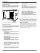
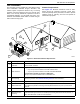
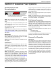
For load conduit, auxiliary power conduit (high voltage),
and control wiring conduit (low voltage), see unit installa-
tion drawings for location and dimensions of the stub-up
ar
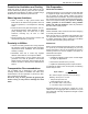
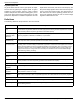
ea. Figure 3-4 illustrates a typical s
tub opening (A).
Figure 3-4. Installation Drawing Stub-Up Detail
(
Typical)
Mounting
Fixed Foundation
Use mounting holes in the base frame to fasten unit to
foundation. Always use hardware of a suitable grade,
size, and style.
Connections
All electrical connections must have flexible sections to
isolate vibration if they connect to the unit base rails. Cor-
rectly support and secure all piping
before installing the
flexible connection.
The surface beneath and beyond the engine and the oil
con
tainment system must be noncombustible to a mini-
mum distance of 12 in (300 mm).
Placement on Roofs, Platforms, and
Other Supporting Structures
Where required to place generator on a roof, platform,
deck, or other supporting structure and an oil contain-
ment system consisting of a curb or dike shall be pro-
vided in accordance with the requirements in NFPA 37
cha
pter 4.1.3 and chapter 6. Contact local building
inspection department or fire department to determine
which noncombustible materials are approved for instal-
lation.
002771
3.9
(100)
4.1 (104.5)
1.9 (50) 0.4 (9)
2.0 (51)
In. (mm)
A