® Installation Guidelines Spark-Ignited Stationary Generators Protector Series 22 kW to 60 kW WARNING Loss of life. This product is not intended to be used in a critical life support application. Failure to adhere to this warning could result in death or serious injury. (000209b) Register your Generac product at: WWW.GENERAC.COM 1-888-GENERAC (888-436-3722) Para español , visita: http://www.generac.com/service-support/product-support-lookup Pour le français, visiter : http://www.generac.
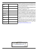
Use this page to record important information about this generator. Model: Serial: Prod Date Week: Volts: LPV Amps: NG Amps: Hz: Phase: Controller P/N: Record the information found on the unit data label on this page. For location of the unit data label, see owner’s manual. The unit has a label plate affixed to the inside partition, to the left of the control panel console.
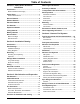
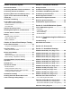
Table of Contents Section 1: Safety Rules & General Information Water Ingress Avoidance ................................. 13 Introduction ..........................................................1 Transportation Recommendations .................. 13 Read This Manual Thoroughly ....................................1 Safety Rules .........................................................1 Proximity to Utilities .......................................... 13 Site Preparation ...............................
Section 5: Electrical System Section 7: Installation Checklists General Information ...........................................29 Safety Checklist ................................................. 43 Connecting Generator Feeder Conductors .....29 Installation Planning Checklist ........................ 43 Connecting Control Circuit Wires ....................30 Foundations and Mounting Checklist ............. 43 Removing Rear Panel and Stub-Up Cover ......30 Ventilation System Checklist ............
Safety Rules & General Information Section 1: Safety Rules & General Information Introduction Thank you for purchasing this compact, high performance, liquid-cooled, engine-driven generator. It is designed to automatically supply electrical power to operate critical loads during a utility power failure. This unit is factory installed in an all-weather enclosure intended exclusively for outdoor installation.
Safety Rules & General Information General Hazards WARNING DANGER Loss of life. Property damage. Installation must always comply with applicable codes, standards, laws and regulations. Failure to do so will result in death or serious injury. (000190) DANGER Automatic start-up. Disconnect utility power and render unit inoperable before working on unit. Failure to do so will result in death or serious injury. (000191) WARNING Loss of life.
Safety Rules & General Information Exhaust Hazards DANGER DANGER Asphyxiation. Running engines produce carbon monoxide, a colorless, odorless, poisonous gas. Carbon monoxide, if not avoided, will result in death or serious injury. (000103) WARNING Asphyxiation. Always use a battery operated carbon monoxide alarm indoors and installed according to the manufacturer’s instructions. Failure to do so could result in death or serious injury. (000178a) WARNING Fire hazard.
Safety Rules & General Information Lifting Hazards WARNING Electrocution. Refer to local codes and standards for safety equipment required when working with a live electrical system. Failure to use required safety equipment could result in death or serious injury. (000257) WARNING Risk of Fire. Unit must be positioned in a manner that prevents combustible material accumulation underneath. Failure to do so could result in death or serious injury.
Safety Rules & General Information WARNING Explosion. Do not dispose of batteries in a fire. Batteries are explosive. Electrolyte solution can cause burns and blindness. If electrolyte contacts skin or eyes, flush with water and seek immediate medical attention. (000162) WARNING Explosion. Batteries emit explosive gases while charging. Keep fire and spark away. Wear protective gear when working with batteries. Failure to do so could result in death or serious injury. (000137a) WARNING Electrical shock.
Safety Rules & General Information and local codes for minimum distances from other structures. • Verify capacity of NG meter or LP tank in regards to providing sufficient fuel for both the unit and other household and operating appliances. This list is not all-inclusive. Check with the Authority Having Local Jurisdiction (AHJ) for any local codes or standards which may be applicable to your jurisdiction. The above listed standards are available from the following internet sources: * www.nfpa.
Installation Planning Section 2: Installation Planning Introduction Inspection DANGER Electrical backfeed. Use only approved switchgear to isolate generator from the normal power source. Failure to do so will result in death, serious injury, and equipment damage.
Installation Planning Use a spreader bar to prevent damage to unit. Failure to use a spreader bar will result in scratches and damage to painted surfaces. See Figure 2-1. Installation drawings show lifting points for rigging and lifting purposes. Always attach lifting and rigging devices at designated points only. Do not use lifting points of the engine or alternator to move generator. ried back to engine area or to fresh air intake vents of nearby buildings.
Site Selection and Preparation Section 3: Site Selection and Preparation Site Selection Site selection is critical for safe generator operation. It is important to discuss these factors with the installer when selecting a site for generator installation: • Carbon monoxide • Fire prevention • Fresh air for ventilation and cooling • Water ingress prevention • Proximity to utilities • Suitable mounting surface The following pages describe each of these factors in detail.
Site Selection and Preparation Potential CO Entry Points Protect the Structure See Figure 3-1. Generator exhaust can enter a structure through large openings, such as windows and doors. However, exhaust and CO can also seep into the structure through smaller, less obvious openings. Verify structure itself is correctly caulked and sealed to prevent air from leaking in or out. Voids, cracks, or openings around windows, doors, soffits, pipes, and vents can allow exhaust gas to be drawn into the structure.
Site Selection and Preparation Fire Prevention The generator must be installed at a safe distance away from combustible materials. Engine, alternator, and exhaust system components become very hot during operation. Fire risk increases if unit is not correctly ventilated, is not correctly maintained, operates too close to combustible materials, or if fuel leaks exist. Also, accumulations of flammable debris within or outside the generator enclosure may ignite. Distance Requirements See Figure 3-2.
Site Selection and Preparation Fire Codes, Standards, and Guidelines Generator installation must comply strictly with ICC IFGC, NFPA 37, NFPA 54, NFPA 58, and NFPA 70 standards. These standards prescribe the minimum safe clearances around and above the generator enclosure. NFPA 37 NFPA 37 is the The National Fire Protection Association’s standard for the installation and use of stationary combustion engines.
Site Selection and Preparation Fresh Air for Ventilation and Cooling Site Preparation Install unit where air inlet and outlet openings will not become obstructed by leaves, grass, snow, etc. If prevailing winds will cause blowing or drifting, consider using a windbreak at a safe distance to protect the unit. Generator Foundation Water Ingress Avoidance • Select a location on high ground where water levels will not rise and flood the generator.
Site Selection and Preparation Stub-Up Area For load conduit, auxiliary power conduit (high voltage), and control wiring conduit (low voltage), see unit installation drawings for location and dimensions of the stub-up area. Figure 3-4 illustrates a typical stub opening (A). In.
Gaseous Fuel Systems Section 4: Gaseous Fuel Systems Fuel Requirements and Recommendations DANGER Explosion and fire. Fuel and vapors are extremely flammable and explosive. No leakage of fuel is permitted. Keep fire and spark away. Failure to do so will result in death or serious injury. (000192) NOTE: NG is lighter than air and will collect in high areas. LP gas is heavier than air and will settle in low areas. LP gas should only use a vapor withdrawal system.
Gaseous Fuel Systems Liquid Propane Gas LP gas is heavier than air. The LP gas vapors are explosive and can be ignited by the slightest spark. LP gas is supplied by liquid propane stored in tanks. Propane exists in its liquid form at or below its boiling point (-44 º F [-42 °C]) as well as when stored under pressure. LP tank pressure is dependent on ambient temperature and the liquid volume in the tank, and can be over 200 psi (1,379 kPa).
Gaseous Fuel Systems Gaseous Fuel Systems NG System Primary Regulator Outlet The utility gas provider will provide the gas meter. Contact utility gas provider to verify they offer a gas meter that will deliver a sufficient fuel supply. Local utility is also responsible for providing fuel at sufficient volume and pressure to operate the primary regulator. Primary regulator can then provide the correct volume of fuel at the required pressure to generator.
Gaseous Fuel Systems E D A C D A B 009331 A Manual fuel shutoff valve C Primary regulator E Unit mounted regulator B Sediment trap D Flexible fuel line — — Figure 4-1.
Gaseous Fuel Systems LP Gas System LP gas uses vapors formed above liquid propane in supply tank. The maximum tank fill capacity is 80% and a minimum of approximately 20% of tank capacity is needed for fuel expansion from liquid to vapor state. Fuel pressure and volume requirements for a LP gas system at the connection point of the generator are listed on the unit specification sheet. Pressure regulation for vapor withdrawal systems is typically a two-step process.
Gaseous Fuel Systems Fuel Pressure Regulators General A common cause of a generator not operating correctly is incorrect sizing and installation of gaseous fuel supply system between gas meter (utility source) and generator connection.
Gaseous Fuel Systems Fuel Pressure Regulator Sizing Fuel pressure regulators are designed to automatically adjust flow to meet downstream demand at a required pressure. The typical regulator installed as the primary regulator for a generator is of the direct acting, internally registered design. “Direct acting” means the pressure sensing element acts directly to open the fuel valve and control flow to load while maintaining desired pressure.
Gaseous Fuel Systems Pipe Sizing Considerations General • Install supplied or recommended length of flexible Contact a local fuel distributor or licensed installer when sizing and installing piping for any gaseous fuel supply system. When using a local fuel distributor or installer, verify they have correct documentation to support their recommendations. Fuel system requirements and best practices conveyed in this manual must be provided to the representative responsible for sizing fuel system.
Gaseous Fuel Systems Table 4-2. LP Gas Pipe Sizing LP Gas 11–14 in of Water Column (2.74–3.48 kPa) Table values are maximum pipe run in ft (m) kW 0.75 in (1.9 cm) 1 in (2.5 cm) 1.25 in (3.2 cm) 1.5 in (3.8 cm) 2 in (5.1 cm) 2.5 in (6.4 cm) 3 in (7.7 cm) RG 22 20 (5.1) 100 (30.45) 400 (121.9) — — — — 25 and 30 50 (12.7) 200 (50.8) 800 (243.8) — — — — 27 15 (4.6) 70 (21.4) 300 (91.4) 625 (190.5) — — — 32 10 (2.5) 60 (18.3) 280 (85.3) 550 (167.6) — — — 36 — 20 (5.
Gaseous Fuel Systems generator will list fuel consumption rate, usually in ft3/hr. To convert CFH to BTU/hr, multiply by 2,520. • Fuel consumption rate in gallons per hour (gph) with generator at 100% load. To convert CFH (propane vapor) to gph, divide by 36.38. To convert BTU/hr to gph, divide by 91,502. • Desired run time. • Minimum operating temperature expected.
Gaseous Fuel Systems Table 4-3. Vaporization Rates Minimum Operating Temperature °F (°C) Tank Vaporization Capacity BTU/hr (MJ/hr) 150 (567.8) 40 (4.4) 20 (-6.6) 0 (-17.8) 325 (1,230.3) 195 (768.2) 500 (1,892.7) Total Tank Capacity gal (L) Available Tank Capacity gal (L) See Note 1 See Note 2 250 (946.4) Length in (cm) Diameter in (cm) 507,600 (535.5) 338,400 (357) 169,200 (178.5) 94 (238.8) 30 (76.2) 40 (4.4) 20 (-6.6) 0 (-17.8) 642,600 (683.3) 428,400 (452) 214,200 (226) 119 (302.
Gaseous Fuel Systems Final Operating Test A correctly configured and sized fuel system provides the fuel volume and fuel pressure required for the generator set to operate correctly in all modes of operation. To verify correct fuel system operation, a series of tests must be performed as described below. sure when cranking, while running at no load, and while running at full load. See C of Figure 4-5.
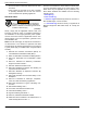
Gaseous Fuel Systems B A C Gauge Adapter 1/8 Inch Diameter Probe Part No. 0K2341 009107 Figure 4-5. Fuel Pressure Test Points Final Test Procedure The following test must be performed at startup to document and validate fuel system operation. It requires a load bank connected to the unit, or a combination of load bank and system load, to bring unit to its full rated kW load capacity. Measure fuel supply pressure under each of the following conditions: 1.
Gaseous Fuel Systems This page intentionally left blank.
Electrical System Section 5: Electrical System General Information All wiring must be correctly sized, routed, supported, and connected. All wiring must comply with NEC and local codes. The generator uses Customer Connection Interface (CCI) panels to separate high voltage and customer control wiring connections. These two panels are clearly labeled. Wiring diagrams for each specific unit show connection points in their corresponding sections.
Electrical System Connecting Control Circuit Wires Table 5-1. Frame Breakers Control system interconnections may consist of N1, N2, and T1, and leads 23 and 194. The generator control wiring is a Class 1 signaling circuit. See instruction manual of specific engine generator for wiring connection details. Recommended wire gauge sizes for wiring depends on length of wire, as recommended in the following chart: Maximum Wire Length Recommended Wire Size 1–115 ft (0.30–35 m) No.
Electrical System mation regarding wire type, temperature rating, size range, and wire lug torque specifications, see Table 5-1 and Table 5-2. Always see NEC tables for specific requirements. NOTE: RTS Series Transfer Switch Without T1 Fuse/ Connection: Use a 120 volt generator protected circuit from the panel board to power the battery charger circuit (dedicated 15/20 amp circuit).
Electrical System Two-Wire Start To convert control panel to two-wire start transfer switch mode of operation, see dealer for panel conversion and connection of terminals 178 and 183 in TB3. Use a 120 volt generator protected circuit from the panel board to power the battery charger circuit (dedicated 15/20 amp circuit). The generator controller will have to be programmed for two-wire start by an IASD.
Electrical System NOTE: The following table is provided for reference purposes only. See latest NEC, state, and local AHJ requirements for correct sizing. Table 5-2. Control Wire Length/Size See latest NEC, state, and local AHJ requirements for details. • Install power and control wires as per NEC require- ments. In a three-phase system, all power conduits from the generator must contain all three phases. Maximum Wire Length Recommended Wire Size 1–115 ft (0.30–35 m) No.
Electrical System 2. Grasp battery strap (B) and lift battery. WARNING Environmental Hazard. Always recycle batteries at an official recycling center in accordance with all local laws and regulations. Failure to do so could result in environmental damage, death, or serious injury. (000228) Always recycle batteries in accordance with local laws and regulations. Contact your local solid waste collection site or recycling facility to obtain information on local recycling processes.
Control Panel Startup / Testing Section 6: Control Panel Startup / Testing Control Panel Interface Generator Setup The control panel interface is located behind the door on the alternator end of the enclosure. Controller will light up when battery power is applied to generator during the installation process. Generator still needs to be activated before it will automatically run in event of a power outage. See Activate Unit.
Control Panel Startup / Testing Before Initial Startup system during installation. Reset control board by pressing OFF button and ENTER button, and restart up to two more times if necessary. If unit fails to start, contact an IASD for assistance. CAUTION Engine damage. Verify proper type and quantity of engine oil prior to starting engine. Failure to do so could result in engine damage.
Installation Guidelines For Spark-Ignited Stationary Generators * ENTER Set Exercise Install Wizard ENTER * ENTER ENTER Quiet Test Mode + yes + no - - 0 + Select Min (0-59) * Switched to “OFF” Hours of Protection 0 (H) - 14 + * ENTER ENTER ENTER Select Hour (0-23) - 2 + Select Month (1-12) Note: If language was previously programmed this goes directly to “Select Hour” Defaults to English if not selected. Install Wizard SEEPROM V 1.01 GUI FW V 1.01 HARDWARE V 1.05 FIRMWARE V 1.
Control Panel Startup / Testing Activate Unit Display Reads: Up Arrow = (+) Language - English + Generator Active is displayed on the LCD screen when the unit is first powered up. After displaying firmware and hardware version codes, as well as other system information, the Install Wizard is launched, and the Language screen is displayed. If the wrong language is selected, it may be changed later using the Edit menu. Use UP ARROW or DOWN ARROW to scroll to desired language.
Control Panel Startup / Testing Operational Checks NOTE: The following procedures require special tools and skills. Contact a Generac dealer or an IASD to perform these tasks. Electrical Checks DANGER Electrocution. High voltage is present at transfer switch and terminals. Contact with live terminals will result in death or serious injury. (000129) NOTE: Verify all power and control wiring is correctly terminated in the generator and corresponding location in transfer switch.
Control Panel Startup / Testing 12. Turn off electrical loads when utility supply voltage is compatible with transfer switch and load circuit ratings. 13. Set MLCB on generator control panel to OFF (OPEN). Checking Automatic Operation Proceed as follows to check system for correct automatic operation: 14. Allow engine to run at no-load for 2–5 minutes. 1. Verify generator is in OFF mode. Red LED above OFF on control panel illuminates to verify system is OFF. 15.
Control Panel Startup / Testing Shutting Generator Down While Under Load or During a Utility Outage DANGER Automatic start-up. Disconnect utility power and render unit inoperable before working on unit. Failure to do so will result in death or serious injury. (000191) IMPORTANT NOTE: If user ever finds it necessary to turn generator OFF during prolonged utility outages to conserve fuel or perform maintenance, alert them to these important steps: To turn generator OFF (while running in AUTO and online): 1.
Control Panel Startup / Testing This page intentionally left blank.
Installation Checklists Section 7: Installation Checklists Safety Checklist Foundations and Mounting Checklist NOTE: See Safety Rules & General Information for more information. NOTE: See Site Selection and Preparation for more information.
Installation Checklists Ventilation System Checklist NOTE: See Site Selection and Preparation for more information.
Installation Checklists Electrical System Checklist NOTE: See Electrical System for more information.
Installation Checklists This page intentionally left blank.
Lube Oil Maintainer System Section 8: Lube Oil Maintainer System Lube Oil Maintainer System NOTE: Close oil shutoff valve when changing engine oil to avoid draining clean oil in the oil supply tank with the crankcase oil. See Oil Shutoff Valve. Description The 36 kW, 45 kW, and 60 kW models are equipped with a lube oil maintainer system. The lube oil maintainer system is factory-installed and factory-calibrated to the correct engine-running crankcase oil level.
Lube Oil Maintainer System Oil Shutoff Valve See Figure 8-3. Close oil shutoff valve when draining engine crankcase oil to avoid draining clean oil from supply tank. 009378 Figure 8-3. Oil Shutoff Valve (Shown in Open Position) Open oil shutoff valve after filling crankcase with clean oil to allow operation of lube oil maintainer system. O E A F B N G C H M D F L B J K 001756 Figure 8-4.
Troubleshooting/Quick Reference Guide Section 9: Troubleshooting/Quick Reference Guide Troubleshooting Problem Cause Blown fuse. Correction Correct short circuit condition by replacing 7.5 amp fuse in generator control panel. Loose, corroded, or faulty battery cables. Engine will not crank Faulty starter contact. Tighten, clean, or replace as necessary. Contact an IASD for assistance. Faulty starter motor. Engine cranks but will not start Engine starts hard and runs rough Discharged battery.
Troubleshooting/Quick Reference Guide Quick Reference Guide To clear an active alarm, press the ENTER button twice and then press AUTO. If the alarm reoccurs, contact an IASD. Active Alarm LED Problem Things to Check NONE GREEN Unit running in AUTO but no power in house. Check MLCB. HIGH TEMPERATURE RED Unit shuts down during operation. Inspect ventilation around generator, Check LED’s / Screen intake, exhaust, and rear of generator. If no for alarms.
Troubleshooting/Quick Reference Guide Active Alarm LED Problem Things to Check Solution LOW BATTERY YELLOW Yellow LED illuminated in any state. See screen for additional information. Clear alarm. Check battery option in control menu. If it states battery is GOOD, contact an IASD. If it states CHECK BATTERY, replace battery. BATTERY PROBLEM YELLOW Yellow LED illuminated in any state. See screen for additional information. Contact an IASD for assistance.
Troubleshooting/Quick Reference Guide This page intentionally left blank.
Accessories Section 10: Accessories Performance enhancing accessories are available for liquid-cooled generators. Item Description Part Number Cold Weather Kit G006175-0—25 & 30 kW G005630-1—36, 45, & 60 kW Recommended in areas where temperatures fall below 32 °F (0 °C). Extreme Cold Weather Kit Engine block heater. Used in conjunction with the appropriate Cold Weather Kit. G006174-0—25 & 30 kW G005616-0—36, 45, & 60 kW NOTE: Engine oil must be replaced with synthetic oil.
Accessories This page intentionally left blank.
Installation Drawings Section 11: Installation Drawings 0K8420-D 25/30 kW (1.5 L) Page 1 of 2 BATTERY 12V GROUP 26 NEGATIVE GROUND P/N: 077483 RADIATOR/EXHAUST DISCHARGE AIR (BOTH SIDES) AIR INTAKE (BOTH SIDES) 665.5 [26.2"] CENTER OF GRAVITY (SEE NOTE 5) SERVICE ITEM 1.5L NOTES: OIL FILL CAP EITHER DOOR OIL DIP STICK RIGHT DOOR OIL FILTER RIGHT DOOR OIL DRAIN HOSE RIGHT DOOR 1. MINIMUM CONCRETE PAD SIZE: 929.6 (36.6") X 1732.3 (68.2") LONG.
Installation Drawings 0K8420-D 25/30 kW (1.5 L) Page 2 of 2 45 [1.8] TYP 13.5 X 29.5 MOUNTING SLOTS 4X 1380 [54.3] TYP MOUNTING SLOT CENTERS * NOTE - STUB-UP AREA FOR HIGH AND LOW VOLTAGE CONNECTIONS. CIRCUIT BREAKER, NEUTRAL AND CUSTOMER CONNECTION OPENING. 674 [26.5] HIGH AND LOW VOLTAGE STUB-UP AREA 104.5 [4.11417] *STUB-UP AREA TOP VIEW 1345 [53.0] 50 [2.0] 100 [3.9] *STUB-UP AREA 9 [.4] 51 [2.0] 226 [8.9] 735 [28.9] REMOVABLE STUB-UP COVER 96 [3.8] 27 [1.0] TYP 723 [28.
Installation Drawings 0K8624-D 22/27 kW (2.4 L) Page 1 of 2 $ & = ^ <$ $ #; $ $% ! $ $ ' $ ! ' #; $ $% ! & $ ' < $ & ! $$ ! ! $ ! $ ; & &<& $ > @ # \% ^ # \% ! $ < $< < ! < $
Installation Drawings 0K8624-D 22/27 kW (2.
Installation Drawings 0K8636-C 36/45 kW (2.
Installation Drawings 0K8636-C 36/45 kW (2.
Installation Drawings 0K9268-E 32/38 kW (2.
Installation Drawings 0K9268-E 32/38 kW (2.
Installation Drawings 0L2090-C 60 kW (2.
Installation Drawings 0L2090-C 60 kW (2.
Installation Drawings 0K9243-C 48 kW (5.4 L) Page 1 of 2 $ & = ^ <$ $ #; $ $% ; < = @ ' #; $ $% $ ! $ ! $ ; $@ & &<& $ > @ # \% ^ # \% ! $ < $< < ! < $ $
Installation Drawings 0K9243-C 48 kW (5.
Installation Drawings Alternator AC Lead Connections The electrical wires in the unit’s AC connection (lower) panel should be installed according to number of leads and voltage/phase required for the application. The voltage and phase are described on the generator data label. The number of lead wires can be identified using the Specifications section and power output rating on the generator data label.
Installation Drawings B Three-Phase Alternators (“Delta” Configuration) E1 S4 S4 S6 S5 S3 E3 The Stationary Emergency Generator is designed to supply three-phase electrical loads. Electric power is produced in the alternator power windings. These windings were factory-connected to the main circuit breaker with a “Delta” configuration as shown in Figure 11-7 and Figure 11-8. S1 S1 00 L-L A Rated voltage between circuit breaker terminals E1–E2, E1–E3 and E2–E3 is 240V.
Installation Drawings Alternator Wiring Diagram (1 of 4) Installation Guidelines For Spark-Ignited Stationary Generators 69
Installation Drawings Alternator Wiring Diagram (2 of 4) 70 Installation Guidelines For Spark-Ignited Stationary Generators
Installation Drawings Alternator Wiring Diagram (3 of 4) Installation Guidelines For Spark-Ignited Stationary Generators 71
Installation Drawings Alternator Wiring Diagram (4 of 4) 72 Installation Guidelines For Spark-Ignited Stationary Generators
Installation Drawings This page intentionally left blank.
Installation Drawings This page intentionally left blank.
® Part No. 0K8419 Rev. F 06/11/19 ©2019 Generac Power Systems, Inc. All rights reserved Specifications are subject to change without notice. No reproduction allowed in any form without prior written consent from Generac Power Systems, Inc. Generac Power Systems, Inc. S45 W29290 Hwy. 59 Waukesha, WI 53189 1-888-GENERAC (1-888-436-3722) www.generac.