
Install Manual


Installation Drawings
54 Installation Guidelines for Protector Diesel Generators
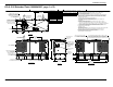
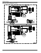
Figure 8-4. Stator Power Winding Connections—
3-phase, 120/208V (6 Lead)
Figure 8-5. Stator Power Winding Connections—
3-phase, 120/208V (12 Lead)
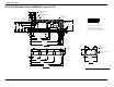
Figure 8-6. Stator Power Winding Connections—
3-phase, 346/600V (6 Lead)
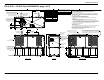
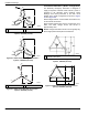
Three-Phase Alternators (“Delta” Configuration)
The Stationary Emergency Generator is designed to
supply three-phase electrical loads. Electric power is
produced in the alternator power windings. These
windings were factory-connected to the main circuit
breaker with a “Delta” configuration as shown in Figure
8-7 and Figure 8-8.
Rated voltage between circuit breaker terminals E1–E2,
E1–E3 and E2–E3 is 240V.
Rated voltage between E2 and the neutral point 00 is
208V. The rated voltage E1–00 and E3–00 is
approximately 120V.
NOTE: Voltage measured from E2 to 00 can greatly vary
when single-phase load is placed on alternator.
Figure 8-7. Stator Power Winding Connections—
3-phase, 120/240V (6 Lead)
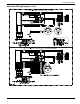
Figure 8-8. Stator Power Winding Connections—
3-phase, 120/240V (12 Lead)
A Neutral B Internal connections
A Neutral B Internal connections
E3 E2
00
E1
L-L
L-N
S1
S1
S4
S4
S6
S6
S3
S3
S5
S5
S2
S2
006480
B
A
E3
E2
E1
L-L
L-N
S7
S1
S10
S4
S12
S6
S9
S3
S5
S11
S2
S8
006481
E1
S1
S6
S5
S4
S2
E2
S3
E3
L - N
L - L
00
006482
B
A
B Internal connections
006483
B
240 VAC
120 VAC
120 VAC
240 VAC
240 VAC
S2 S12
S11
S1
NB
S10
S3
E1
E3
E2
S5
S8
S9
S6
208 VAC
006484