
Install Manual


Electrical System
Installation Guidelines for Protector Diesel Generators 25
• When working on battery, always remove watches,
rings, or other metal objects, and only use tools
that have insulated handles. Do not lay tools or
metal parts on top of battery.
• Discharge static electricity from body before touch-
ing battery by first touching a grounded metal sur-
face.
• Wear full eye protection, protective clothing, and
gloves when handling a battery.
• Immediately wash down spilled electrolyte with an
acid neutralizing agent. Use a solution of 1 lb (500
g) bicarbonate of soda to 1 gal (4 L) of water. Add
the bicarbonate of soda solution until evidence of
reaction (foaming) has ceased. Flush resulting liq-
uid with water.
Battery Requirements
The ability to start the engine depends upon battery
capacity, ambient temperatures, and coolant and oil tem-
peratures. The engine/generator set data sheet lists mini-
mum recommended battery capacity at various ambient
temperatures. The recommended battery capacities are
listed under cold cranking amps (CCA) at 0 °F (−18 °C).
The recommended battery for this unit is Group 27F, 700
CCA. 30kW units can be upgraded to a Group 31 925
CCA battery.
NOTE: Battery capacities decrease as ambient tempera-
tures decrease, so it is important to specify batteries with
the appropriate CCA rating at a temperature no higher
than minimum ambient temperature for the application.
Battery Installation
Fill battery with correct electrolyte fluid if necessary and
have battery fully charged before installing it.
Use appropriate tools when working with battery termi-
nals. The use of terminal pullers, expansion pliers, and
terminal cleaning brushes will greatly extend the life of
battery terminals.
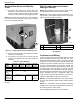
1. See Figure 5-6. Install rubber protective cover (B)
over positive (+) battery terminal.
2. Grasp battery strap (A) and lift battery.
3. Set battery onto battery tray.
4. Tighten two screws with nylon washers to secure
hold-down clamp to battery tray, or tighten strap
over top of battery.
5. Remove rubber protective cover from positive (+)
battery terminal.
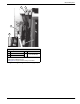
6. Install positive battery cable (D) (red) on positive
(+) battery terminal.
7. Install negative battery cable (C) (black) on nega-
tive (-) battery terminal.
NOTE: The unit is equipped with an internal battery
charger. The internal battery charger is powered by the
T1 wire. Verify power supply (T1 wire) has been safely
disconnected before performing any work on battery.
Figure 5-6. Battery Cable Connections
-
+
000621
001499
A
B
C
D