
Install Manual


Electrical System
22 Installation Guidelines for Protector Diesel Generators
Control Wiring Connections
The control wire customer connection block is where all
of control wiring is connected.
NOTE: All wiring must comply with NEC, state, and local
AHJ requirements. Control wiring shall be installed per
the requirements of NEC Articles 300.3(C) and 725.46. If
installing conductors with different voltage insulation rat-
ings, a 600V rated electrical sleeve is provided and can
be found in the manual bag.
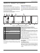
See Figure 5-4. Depending on the type of system, con-
trol wiring includes the following. (Wire colors shown for
illustration purposes only):
Figure 5-4. Control Wiring Connections (Typical)
RTS Series Transfer Switch With T1 Fuse/
Connection
NOTE: The control wire customer connections require
the use of Class 1 Wiring Methods. Always follow the
standards and methods appropriate to circuits being
wired.
NOTE: T1 is the 120 VAC power supply for control panel
battery charger. This circuit must be powered whether
transfer switch is in utility or standby mode. Control board
will generate a warning (Battery Charge AC Fail) if circuit
loses power.
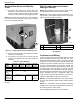
NOTE: Observe maximum wire size for terminal strip
connections shown in unit wiring diagram.
(1) For battery charging, connect neutral in TB2 to neutral
in transfer switch. See NOTE below for transfer switches
without T1.
(2) Connect T1 in TB2 to T1 in transfer switch. This is
120 volt supply to unit's battery charger (normal RTS
transfer switch).
(3) (4) Connect N1, N2 sensing wires in TB2 to N1 and
N2 in transfer switch. These two wires are utility sensing
wires.
(5) (6) Connect 23 in TB3 to 23 in transfer switch. Con-
nect 194 in TB3 to 194 in transfer switch. These are
transfer switch control wires.
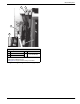
RTS Series Transfer Switch Without T1 Fuse/
Connection
Use a 120 volt generator protected circuit from the panel
board to power the battery charger circuit (dedicated 15/
20 amp circuit). See installation manual.
Two-Wire Start
To convert transfer switches to two-wire start mode of
operation, contact an IASD for panel conversion and con-
nection of terminals 178 and 183 in TB3. Use a 120 volt
generator protected circuit from panel board to power
battery charger circuit (dedicated 15/20 amp circuit).
The generator controller will have to be re-programmed
for two-wire start by an IASD.
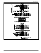
TB2 Terminal Block
Terminal Function Voltages
1
Neutral Neutral for T1 battery charger Neutral
2
T1 Power for T1 battery charger 120 VAC
3
N2 Utility Sensing from transfer switch 208-277 VAC
4
N1 Utility Sensing from transfer switch 208-277 VAC
TB3 Terminal Block
Terminal Function Voltages
A
178 Two wire start control [GTS] 5-12 VDC
B
183 Two wire start control [GTS] 5-12 VDC
5
23 Transfer relay control wire 12-0 VDC
6
194 Power for transfer relay 12 VDC
1
2
3
4
A
B
5
6