
Recreational Vehicle Generator Diagnostic Repair Manual


Section 7
DIAGNOSTIC TESTS
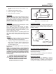
Figure 7-34. – Cylinder Balance Test
The cylinder balance test will also detect a cylinder
that is not functioning. When grounding out one cylin-
der there will be no RPM loss. When the other cylin-
der is grounded out the engine will stop.
TEST 30 - CHECK SPARK PLUGS
DISCUSSION:
During Test 29, if spark jumped the tester gap, the
ignition system must be functioning properly. However,
if the engine misses the spark plug itself may be
fouled.
PROCEDURE:
Remove spark plugs. Clean with a commercial sol-
vent. DO NOT BLAST CLEAN SPARK PLUGS.
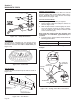
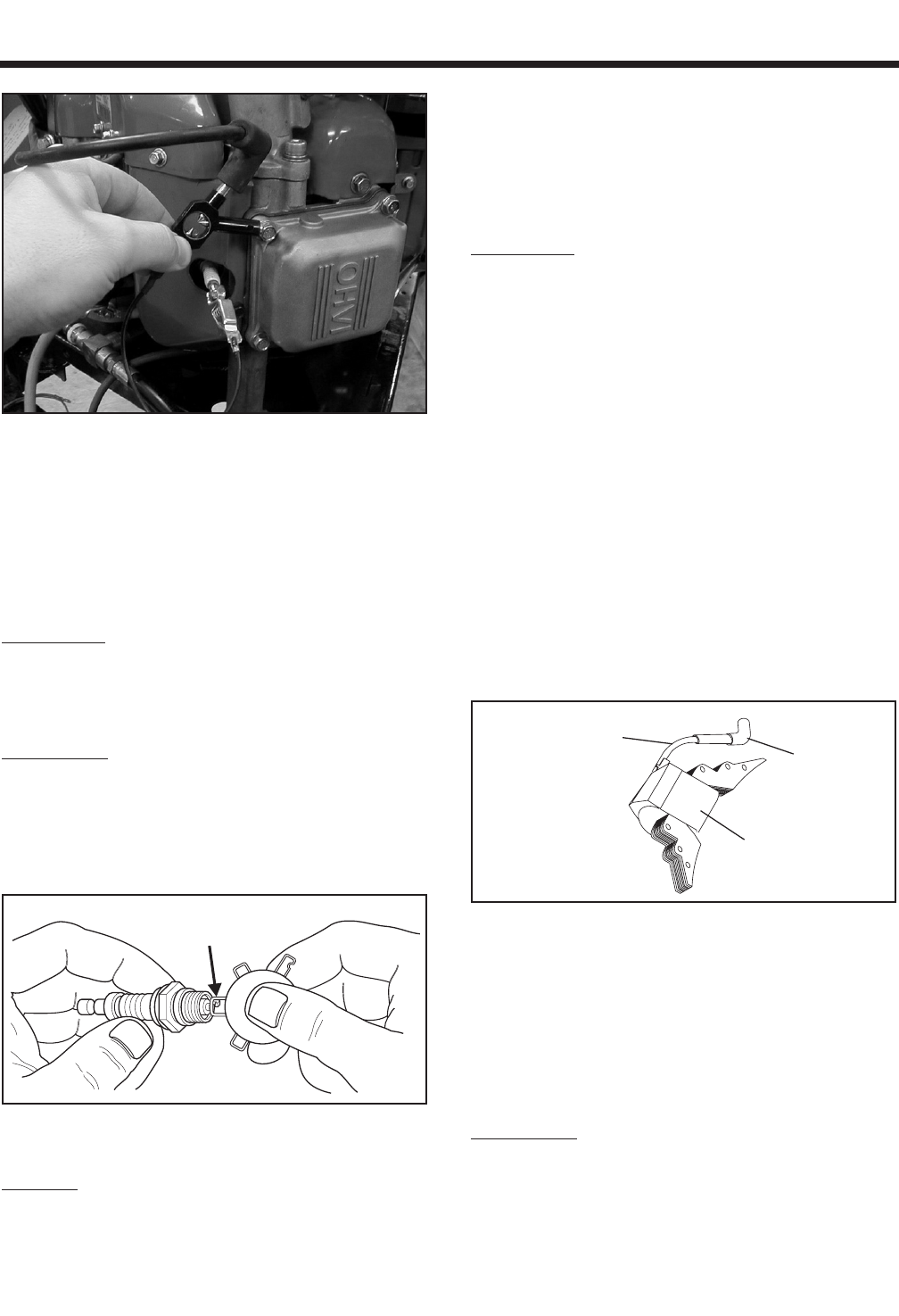
Replace spark plugs if badly fouled, if ceramic is
cracked, or if badly worn or damaged. Set gap to
0.030 inch (0.76mm). Use a NGK BPR6HS (or equiv-
alent) replacement spark plug.
SET PLUG GAP AT 0.030 inch
(0.76 mm)
Figure 7-35 – Setting Spark Plug Gap
RESULTS:
1. Clean and regap or replace sparks plug as neces-
sary.
2. If spark plugs are good for gasoline models, go to
Test 33. For LPG models, go to Test 32.
TEST 31 – CHECK AND ADJUST IGNITION
MAGNETOS
DISCUSSION:
The ignition system used on GT-530 engines is a
solid-state (breakerless) type. The system utilizes a
magnet on the engine flywheel to induce a relatively
low voltage into an ignition magneto assembly. Ignition
magneto internal components increase the voltage
and deliver the resulting high voltage across the spark
plug gap.
The ignition magneto houses a solid state-circuit
board that controls ignition timing. Timing is fixed and
spark advance is automatic.
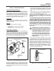
Major components of the ignition system include (a)
two ignition magneto assemblies, (b) the spark plugs,
(c) the engine control printed circuit board and (d) the
engine flywheel.
Solid-state components encapsulated in the ignition
magneto are not accessible and cannot be serviced. If
the magneto is defective, the entire assembly must be
replaced. The air gap between the magneto and the
flywheel magnet is between 0.012” to 0.015”.
The ignition magneto assembly (Figure 7-36) consists
of (a) ignition magneto, (b) spark plug high tension
lead and (c) spark plug boot.
SPARK PLUG
HIGH TENSION
LEAD
SPARK
PLUG
BOOT
IGNITION COIL
Figure 7-36. – Ignition Magneto Assembly
In Test 29, a spark tester was used to check for
engine ignition. If sparking or weak spark occurred,
one possible cause might be the ignition magneto(s).
This test consists of adjusting the air gap between the
ignition magneto(s) and the flywheel. The flywheel
and flywheel key will also be checked during this test.
If no sparking occurs, the ground harness may be at
fault.
PROCEDURE:
1. Disconnect the J1 connector from the Printed
Circuit Board. Carefully remove Wire 18A from Pin
Location J1-14. Connect the J1 connector back to
the Printed Circuit Board. Repeat Test 29 “Check
Ignition Spark”. If the unit now produces spark go
Page 55