
Recreational Vehicle Generator Diagnostic Repair Manual
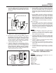


3. Connect the test leads of a VOM across the
switch terminals. The meter should read “Infinity”.
4. Heat the oil. When oil temperature reach-
es approximately 270-284° F., the switch con-
tacts should close and the meter should read
“Continuity”.
Figure 7-46. – Testing Oil Temperature Switch
RESULTS:
1. If the Oil Temperature Switch fails Step 3 or Step
4, replace the Oil Temperature Switch.
2. If the Oil Temperature Switch is good, an overheat
condition may be occurring. Verify that the installa-
tion of the generator is within specified tolerances.
The generator must receive the proper amount of
incoming air, and also be able to exhaust the
cooling air with NO RESTRICTIONS. Check to
be sure that the exhaust pipe is not under the
air intake. Refer to the Owner’s and Installation
Manual for proper installation specifications. If
installation is correct, go to Test 20.
TEST 39 – CHECK WIRE 85 FOR CONTINUITY
PROCEDURE:
1. Disconnect the J1 Connector from the Printed
Circuit Board.
2. Locate Pin Location J1-7 on the harness end of
the J1 Connector.
3. Remove Wire 85 from the High Oil Temperature
switch (HOT).
4. Set a VOM to its “Rx1” scale and zero the meter.
5. Insert one meter test lead into the end of Wire
85 disconnected from the HOT. Insert the other
meter test lead into Pin Location J1-7 on the har-
ness end of the J1 Connector.
RESULTS:
1. If “Continuity” is not indicated, repair or replace
Wire 85.
2. If “Continuity” is indicated, replace the Printed
Circuit Board.
TEST 40 – TEST CHOKE HEATER
DISCUSSION:
The Choke Heater is a sensitive heating element
wrapped around a temperature sensitive Bi-Metal
strip. The BI-METAL HEATER ASSEMBLY positions
the Choke Plate during startup. Once running, the Bi-
Metal Heater Assembly will also allow the Choke Plate
to fully open. Power for the heater element is supplied
from Wire 14 to assist the Bi-Metal Heater Assembly
in opening the Choke Plate after starting. Failure of
the Choke Plate to open will cause an excessively rich
fuel-air mixture and engine performance will suffer.
PROCEDURE:
1. Verify that the Choke Plate on the carburetor is
mechanically free to move and is not binding. If
the engine runs rough, check the operation of the
BI-METAL HEATER ASSEMBLY. Allow the engine
to run for five minutes, then inspect the choke
position. The Bi-Metal strip should have been
heated by the Choke Heater and should have
expanded to allow the Choke Plate to open fully.
2. If the Choke Plate did not open in Step 1, check
the Choke Heater. Set the VOM to measure DC
voltage. Disconnect Connector 3 at the Choke
Assembly. Connect the positive (+) meter test
lead to Wire 14 (Connector 3, Pin 3) going to the
control panel. Connect the negative (-) meter test
lead to a clean frame ground. Set the Start-Stop
Switch to “START.” Battery voltage should be
measured (see Figure 7-43 on Page 63).
3. If battery voltage was not measured in Step 2,
set the VOM to measure resistance. Disconnect
Connector 3 at the Choke Assembly. Connect
one meter test lead to Wire 14 (Connector 3, Pin
3) going to the control panel. Connect the other
meter test lead to the 4-tab Connector for Wire 14
in the control panel. “Continuity” should be mea-
sured.
SHORT TO GROUND:
Set the VOM to measure resistance. Connect one
meter test lead to Wire 14 (Connector 3, Pin 3) going
to the Bi-Metal Heater Assembly. Connect the other
meter test lead to the exposed steel portion of the Bi-
Metal Heater Assembly. Approximately 37 ohms (±20%)
should be measured. (Current draw of the Bi-Metal
Heater Assembly at nominal voltage is approximately
340 milliamps or 0.340 amps). If “Continuity” is present
the Bi-Metal Heater Assembly has a short to ground.
Page 62
Section 7
DIAGNOSTIC TESTS