
Recreational Vehicle Generator Diagnostic Repair Manual


“Infinity” should be measured. Set the Start-Stop
Switch to “START”. The meter should now read
“Continuity”.
Short to Ground:
3. Set the VOM to measure resistance (“R x 1”
scale). Disconnect Wire 56 from the Starter
Contactor Relay (SCR). Connect one meter test
lead to the SCR terminal from which Wire 56 was
just removed. Connect the other meter test lead to
a clean frame ground. Starter Contactor Relay coil
resistance of 155 ohms should be measured. If
“Continuity” is measured a short to ground exists.
Note: Current draw of the Starter Contactor Relay
coil at nominal voltage is approximately 80ma.
RESULTS:
1. If “Continuity” is not measured in Step 1, repair
or replace Wire 0 between the Starter Contactor
Relay and the ground terminal.
2. If
“
Continuity” was not measured in Step 2 when
the Start-Stop switch was activated to “START”,
replace the Starter Contactor Relay.
3. If “Continuity” is measured in Step 2, go to Test
23.
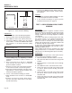
TEST 23 – CHECK STARTER CONTACTOR
DISCUSSION:
The Starter Contactor (SC) must energize and it’s
heavy duty contacts must close or the engine will not
crank. This test will determine if the Starter Contactor
is in working order. The Starter Contactor is connect-
ed to the Starter Motor (see Figure 7-20).
CONNECTING
DIAGRAM
BATTERY
12V
STARTER
SWITCH
PERMANENT MAGNET
30
50
16
STARTER
CONTACTOR
STARTER
MOTOR
STEP 2
TEST POINT
STEP 1
TEST POINT
Figure 7-20. – The Starter Contactor (SC)
PROCEDURE:
1. Carefully inspect the starter motor cable that runs
from the Battery to the Starter Motor. Cable con-
nections should be clean and tight. If connections
are dirty or corroded, remove cable and clean
cable terminals and studs. Replace any cable
that is defective or badly corroded. Set the VOM
to measure DC voltage. Connect the positive
(+) meter test lead to the Starter Contactor stud
that the battery cable is connected to. Connect
the negative (-) meter test lead to a clean frame
ground. Battery voltage should be measured (see
Figure 7-20, STEP 1 TEST POINT).
2. Set the VOM to measure DC voltage. Disconnect
Wire 16 from the Starter Contactor. Connect the
positive (+) meter test lead to Wire 16. Connect
the negative (-) meter test lead to a clean frame
ground. Set the Start-Stop Switch to “START”.
Battery voltage should be indicated. Reconnect
Wire 16 to the Starter Contactor.
3. Set the VOM to measure DC voltage. Connect
the positive (+) meter test lead to the Starter
Contactor stud that has the small jumper wire
connected to the Starter. Connect the negative
(-) meter test lead to a clean frame ground. Set
the Start-Stop Switch to “START”. Battery volt-
age should be measured (see Figure 7-20, STEP 2
TEST POINT).
RESULTS:
1. If battery voltage was not measured in Step 1,
repeat Test 17.
2. If battery voltage was not measured in Step 2,
repair or replace Wire 16 between the Starter
Contactor Relay (SCR) and the Starter Contactor
(SC).
3 If battery voltage was measured in Step 1, but not
in Step 3, replace the Starter Contactor.
4. If battery voltage was measured in Step 3 but the
engine still does not crank, go to Test 24.
TEST 24 – CHECK STARTER MOTOR
CONDITIONS AFFECTING STARTER MOTOR
PERFORMANCE:
1. A binding or seizing condition in the Starter Motor
bearings.
2. A shorted, open or grounded armature.
a. Shorted, armature (wire insulation worn and
wires touching one another). Will be indicated by
low or no RPM.
b. Open armature (wire broken) will be indicated
by low or no RPM and excessive current draw.
c. Grounded armature (wire insulation worn and
wire touching armature lamination or shaft). Will
Page 48
Section 7
DIAGNOSTIC TESTS