
Recreational Vehicle Generator Repair Manual

SSeeccttiioonn 11
GGEENNEERRAATTOORR FFUUNNDDAAMMEENNTTAALLSS
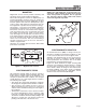
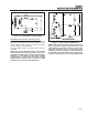
FIELD BOOST
When the engine is cranked during startup, the
engine's starter contactor is energized closed. Battery
current is then delivered to the starter motor and the
engine cranks.
Closure of the starter contactor contacts also delivers
battery voltage to Pin 13 of an Engine Controller cir-
cuit board. The battery current flows through a 47
ohm, 2 watt resistor and a field boost diode, then to
the Rotor via brushes and slip rings. This is called
“Field Boost” current.
Field boost current is delivered to the Rotor only while
the engine is cranking. The effect is to “flash the field”
every time the engine is cranked. Field boost current
helps ensure that sufficient “pickup” voltage is avail-
able on every startup to turn the Voltage Regulator on
and build AC output voltage.
NOTE: Loss of the Field Boost function may or
may not result in loss of AC power winding out-
put. If Rotor residual magnetism alone is suffi-
cient to turn the Regulator on loss of Field Boost
may go unnoticed. However, If residual magnet-
ism alone Is not enough to turn the Regulator on,
loss of the Field Boost function will result In loss
of AC power winding output to the load. The AC
output voltage will then drop to a value commen-
surate with the Rotor's residual magnetism (about
7-12 VAC).
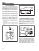
GENERATOR AC CONNECTION SYSTEM
These air-cooled generator sets are equipped with
dual stator AC power windings. These two stator wind-
ings supply electrical power to customer electrical
loads by means of a dual 2-wire connection system.
Generators may be installed to provide the following
outputs:
1. 120 VAC loads only — one load with a maximum total wattage
requirement equal to the generator’s rated power output (in
watts), and 120V across the generator output terminals. Figure
1.8, page 7, shows the generator lead wire connections for
120VAC ONLY.
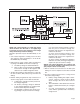
2. 120/240 VAC loads — one load with a maximum total wattage
requirement equal to the generator’s rated power output, and
240V across the generator output terminals; or two separate
loads, each with a maximum total wattage requirement equal to
half of the generator’s rated power output (in watts), and 120V
across the generator output terminals. Figure 1.9 on page 7,
shows the generator lead wire connections for 120/240 VAC
loads.
You can use your generator set to supply electrical
power for operating one of the following electrical
loads:
• QUIETPACT 55G & LP: 120 and/or 240 volts, sin-
gle phase, 60 Hz electrical loads. These loads can
require up to 5500 watts (5.5 kW) of total power,
but cannot exceed 45.8 AC amperes of current at
120 volts or exceed 22.9 AC amperes at 240 volts.
• QUIETPACT 65G & LP: 120 and/or 240 volts, sin-
gle phase, 60 Hz electrical loads. These loads can
require up to 6500 watts (6.5 kW) of total power,
but cannot exceed 54.1 AC amperes of current at
120 volts or exceed 27 AC amperes at 240 volts.
• QUIETPACT 75G & LP: 120 and/or 240 volts, sin-
gle phase, 60 Hz electrical loads. These loads can
require up to 7500 watts (7.5 kW) of total power,
but cannot exceed 62.5 AC amperes of current at
120 volts or exceed 31.2 AC amperes at 240 volts.
CCAAUUTTIIOONN!! DDoo nnoott oovveerrllooaadd tthhee ggeenneerraattoorr.. SSoommee
iinnssttaallllaattiioonnss mmaayy rreeqquuiirree tthhaatt eelleeccttrriiccaall llooaaddss bbee
aalltteerrnnaatteedd ttoo aavvooiidd oovveerrllooaaddiinngg.. AAppppllyyiinngg eexxcceess--
ssiivveellyy hhiigghh eelleeccttrriiccaall llooaaddss mmaayy ddaammaaggee tthhee ggeenn--
eerraattoorr aanndd mmaayy sshhoorrtteenn iittss lliiffee.. AAdddd uupp tthhee rraatteedd
wwaattttss ooff aallll eelleeccttrriiccaall lliigghhttiinngg,, aapppplliiaannccee,, ttooooll aanndd
mmoottoorr llooaaddss tthhee ggeenneerraattoorr wwiillll ppoowweerr aatt oonnee ttiimmee..
TThhiiss ttoottaall sshhoouulldd nnoott bbee ggrreeaatteerr tthhaann tthhee wwaattttaaggee
ccaappaacciittyy ooff tthhee ggeenneerraattoorr.. IIff aann eelleeccttrriiccaall ddeevviiccee
nnaammeeppllaattee ggiivveess oonnllyy vvoollttss aanndd aammppss,, mmuullttiippllyy
vvoollttss ttiimmeess aammppss ttoo oobbttaaiinn wwaattttss ((vvoollttss xx aammppss ==
wwaattttss)).. SSoommee eelleeccttrriicc mmoottoorrss rreeqquuiirree mmoorree wwaattttss
ooff ppoowweerr ((oorr aammppss ooff ccuurrrreenntt)) ffoorr ssttaarrttiinngg tthhaann ffoorr
ccoonnttiinnuuoouuss ooppeerraattiioonn..
LINE BREAKERS (120 VOLTS ONLY):
Protects generator’s AC output circuit against
overload, i.e., prevents unit from exceeding
wattage/amperage capacity. The circuit breaker rat-
ings are as follows:
Page 6
MMooddeell CCiirrccuuiitt BBrreeaakkeerr 11 CCiirrccuuiitt BBrreeaakkeerr 22
QuietPact 55 30A 20A
QuietPact 65 30A 30A
QuietPact 75 35A 35A