QT 3.9L 40kW Model: 005221-0 Serial Number STANDBY GENERATOR OWNER'S MANUAL A new standard of reliability —CAUTION— ONLY QUALIFIED ELECTRICIANS OR CONTRACTORS SHOULD ATTEMPT INSTALLATION! This manual should remain with the unit. Cover026 Rev. 0 09/05 Part No.
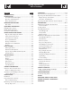
Standby Generator Sets Table of Contents PAGE OPERATION ...........................................................9-1 SAFETY RULES ................................................ 1-1 Generator Control and Operation ................................9-1 INTRODUCTION .....................................................1-3 Operating Unit with Manual Transfer Switch ...............9-1 Read this Manual Thoroughly ...................................1-3 Engine Start-up and Transfer .......................
Standby Generator Sets Important Safety Instructions WARNING: GENERAL HAZARDS • For safety reasons, the manufacturer recommends that this equipment be installed, serviced and repaired by an Authorized Service Dealer or other competent, qualified electrician or installation technician who is familiar with applicable codes, standards and regulations. The operator also must comply with all such codes, standards and regulations.
Standby Generator Sets Important Safety Instructions • Generators installed with an automatic transfer switch will crank and start automatically when normal (utility) source voltage is removed or is below an acceptable preset level. To prevent such automatic start-up and possible injury to personnel, disable the generator’s automatic start circuit (battery cables, etc.) before working on or around the unit. Then, place a “Do Not Operate” tag on the generator control panel and on the transfer switch.
Standby Generator Sets Important Safety Instructions INTRODUCTION This symbol points out potential fire hazard. symbol points out potential electrical shock This hazard. Thank you for purchasing this model of the standby generator set product line. Every effort was expended to make sure that the information and instructions in this manual were both accurate and current at the time the manual was written.
Standby Generator Sets General Information IDENTIFICATION RECORD NOTE: For actual information related to this particular model, please refer to the Manual Drawing Listing located at the end of this manual, or to the data label affixed to the unit. DATA LABEL Every generator set has a DATA LABEL that contains important information pertinent to the generator.
Standby Generator Sets Equipment Description EQUIPMENT DESCRIPTION COOLANT RECOMMENDATIONS This equipment is a revolving field, alternating current generator set. It is powered by a gaseous fueled engine operating at 1800 rpm for 4-pole direct drive units, 3600 rpm for 2-pole direct drive units and 2300 - 3000 rpm for quiet drive gear units. See the Specifications section for exact numbers.
Standby Generator Sets Engine Protective Devices ENGINE PROTECTIVE DEVICES OVERCRANK SHUTDOWN The standby generator may be required to operate for long periods of time without an operator on hand to monitor such engine conditions as coolant temperature, oil pressure or rpm.
Standby Generator Sets Fuel Systems FUEL SYSTEM PROPANE VAPOR WITHDRAWAL FUEL SYSTEM FUEL REQUIREMENTS This type of system utilizes the vapors formed above the liquid fuel in the supply tank. Approximately 10 to 20 percent of the tank capacity is needed for fuel expansion from the liquid to the vapor state. The vapor withdrawal system is generally best suited for smaller engines that require less fuel.
Standby Generator Sets Specifications SPECIFICATIONS Engine Lubrication System Type of Oil Pump ...................................................................... Gear Oil Filter ............................................... Full Flow Spin-on, Cartridge Crankcase Oil Capacity ....................................................4 U.S. qts. GENERATOR Type ............................................................................. Synchronous Rotor Insulation ......................................
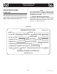
Standby Generator Sets Specifications Figure 1 — Interconnections COLD WEATHER KIT 10. Reverse the procedure to convert back to natural gas. 11. The Dip switch inside the control panel must be in the LP or NG position when switching to different fuels. For cold climates, optional cold weather kit (part number 0F6148) is recommended. The kit includes: • Battery Warmer • 4” Junction Box with hardware • 6 qt. pack 5W-30 synthetic oil (engine) Figure 6.
Standby Generator Sets General Information GENERATOR AC LEAD CONNECTIONS ALTERNATOR POWER WINDING CONNECTIONS See “Voltage Codes”. This generator may be rated at any one of three voltages, either single-phase or three-phase. The electrical wires in the unit’s AC connection (lower) panel should be installed according to the number of leads and the voltage/phase required for the application. If there are any questions regarding lead connection, refer to the wiring diagrams at the back of this manual.
Standby Generator Sets Installation PRIOR TO INITIAL START-UP INSTALLATION Refer to the separate “Installation Guide QT Product Line” supplied with the unit. to initially starting the generator, it must Prior be properly prepared for use. Any attempt to PREPARATION BEFORE START-UP The instructions in this section assume that the standby generator has been properly installed, serviced, tested, adjusted and otherwise prepared for use by a competent, qualified installation contractor.
Standby Generator Sets Installation START-UP CHECKLIST • Check voltage at the generator terminals. • For 3-phase units, check phase rotation at the transfer switch terminals. The generator phase rotation must match the utility phase rotation. • Check for coolant, fuel, oil, and exhaust leaks. • Close the generators main line circuit breaker. • Turn the generator set off. • Connect the UTILITY supply to the transfer switch. • Set the AUTO/OFF/MANUAL switch to AUTO.
Standby Generator Sets Operation GENERATOR CONTROL AND OPERATION not crank the engine continuously for longer Do than 30 seconds, or the heat may Refer to the appropriate control panel operator’s manual for this unit. • • OPERATING UNIT WITH MANUAL TRANSFER SWITCH If the generator was installed in conjunction with a transfer switch capable of manual operation only, the following procedure applies.
Standby Generator Sets Maintenance MAINTENANCE PERFORMED BY AUTHORIZED SERVICE FACILITIES exhaust system parts from this product get The extremely hot and remain hot after shutdown. High grass, weeds, brush, leaves, etc. must remain clear of the exhaust. Such materials may ignite and burn from the heat of the exhaust system. working on the generator, ensure the fol Before lowing: • The AUTO/OFF/MANUAL switch is in the OFF position. • The 15A fuse has been removed from the control box.
Standby Generator Sets Maintenance ENGINE COOLANT CHECK FAN BELT Check coolant level in coolant recovery bottle. See the “Specifications” section. • Inspect fan belts every three months. Replace any damaged, deteriorated, worn or otherwise defective belt. • Check fan belt tension. Thumb pressure, exerted midway between pulleys, should deflect about 3/8 to 5/8 inch. Adjust belt tension as required. • Add recommended coolant mixture as necessary.
Standby Generator Sets Maintenance COOLANT CHANGE 7. Start engine and check for oil leaks. Every year, have an Authorized Service Facility drain, flush and refill the cooling system. See the “Specifications” section for cooling system recommendations. Figure 10.2 - Oil Filter MISCELLANEOUS MAINTENANCE CLEANING THE GENERATOR Keep the generator as clean and as dry as possible. Dirt and moisture that accumulates on internal generator windings have an adverse effect on insulation resistance.
Standby Generator Sets Maintenance BATTERY MAINTENANCE The battery should be inspected per the “Service Schedule” section. The following procedure should be followed for inspection: sure the AUTO/OFF/MANUAL switch is set to Be the OFF position before connecting the battery cables. If the switch is set to AUTO or MANUAL, the generator can crank and start as soon as the battery cables are connected. 1. Inspect the battery posts and cables for tightness and corrosion. Tighten and clean as necessary. 2.
Standby Generator Sets Service Schedule SERVICE SCHEDULE 30 KW - 150 KW STANDBY GAS ENGINE DRIVEN GENERATOR SETS The following is a recommended maintenance schedule for standby gas engine driven generator sets from 30kW to 150 kW in size. The established intervals in the schedule are the maximum recommended when the unit is used in an average service application. They will need to be decreased (performed more frequently) if the unit is used in a severe application.
Standby Generator Sets Service Schedule Maintenance Tasks Level 1 Recommended to be done monthly/ 10 hrs. Level 2 Level 3 Task Required Task Required Comp. to be done Comp. to be done (Date- 3 months/ (DateSemiInitials) Break-in Initials) annually/ 30 hrs. 50 hrs. 1. Disable the unit from operating per the first page warning. 2. Check the engine oil level. Adjust as necessary. 3. Check the engine coolant level. Adjust as necessary. 4. Check the engine coolant thermal protection level.
Standby Generator Sets Service Schedule Maintenance Tasks Level 1 Recommended to be done monthly/ 10 hrs. Level 2 Level 3 Task Required Task Required Comp. to be done Comp. to be done (Date- 3 months/ (DateSemiInitials) Break-in Initials) annually/ 30 hrs. 50 hrs. Level 4 Task Comp. (DateInitials) Required to be done Annually/ 100 hrs. Level5 Task Comp. (DateInitials) Required to be done Biannually/ 250 hrs. Task Comp. (DateInitials) 10.
Standby Generator Sets Service Schedule Maintenance Tasks Level 1 Recommended to be done monthly/ 10 hrs. Level 2 Level 3 Task Required Task Required Comp. to be done Comp. to be done (Date- 3 months/ (DateSemiInitials) Break-in Initials) annually/ 30 hrs. 50 hrs. 18. Start and exercise the unit at full rated load (use a load bank if the site load is not enough) for at least 2 hours looking for leaks, loose connections or components, and abnormal operating conditions. Correct as necessary. 19.
Standby Generator Sets Troubleshooting TROUBLESHOOTING GUIDE PROBLEM CAUSE CORRECTION Engine won’t crank. 1. 15 amp fuse blown. 2. Loose or corroded or defective battery cables. 3. Defective starter contactor. 4. Defective starter motor. 5. Dead or Defective Battery. 6. 5 amp fuse blown. 1. Replace fuse. 2. Tighten, clean or replace battery cables as necessary. 3. Replace contactor.* 4. Replace starter motor.* 5. Remove, change or replace battery. 6. Replace fuse.* Engine cranks but won't start 1.
Standby Generator Sets Notes
1 2 3 4 5 *** 0F3137 0F3188 0F3189 023484N 0F6366B 0F6366A 043180 022264 0C3990 057701 022155 0C2428 0F3824 0A9457 057073 0D5466 0A7822 022237 022241 049226 0C2266 0C2454 022473 022097 0D4698 0F4464 025433 024469 067210A 0D6029 081008 077043J 051713 0F6156 029289 047411 064153B 1 1 1 1 1/2 1 2/4 2/4 2/4 REF 4 4 1 1 2 REF REF 2 2 7 6 8 8 4 REF 1 1 1 1 4 1 1 2 1 1 4 2 0F3328 065469 0D5552 0D5554 0D5556 0D9693 0F0492 048927 023897 022152 022158 0C2454 029289 0F1733 1 1 1 1 4 4 4 4 7 1 1 UL CIRCUIT BREAKER
1 2 3 4 5 6 7 8 9 10 11 12 13 14 15 16 17 18 19 20 21 22 23 24 * 25 * 0F3438 0F3440 0F6188 0F6190 0F3439 0F3441 0F6189 0F6199 0F6655 0F6656 0C9708 SEE ENGINE EV SEE ENGINE EV 0F5536 0E5706 0F7874 0F6124 0F6123 0E6076 023454 077043F 04576100BU 04576100AQ 052646 043123 051779 0A2601 0A2602 0F3398 046526 0C3993 022264 038150 047248 070892 1 1 1 1 1 1 1 1 1 1 1 REF REF 1 1 1 1 1 1 1 1 4 4 4 4 4 1 1 8 8 4 4 4 1 1 RTR 390 30AD1 CPL RTR 390 40AD2 CPL HI-EF ASSY RTR 390 30KD1 CPL ASSY RTR 390 40KD2 CPL STR 390
1 2 3 4 5 6 7 8 9 10 11 12 13 14 15 16 17 18 19 20 21 22 23 24 25 26 27 28 29 30 31 32 33 34 35 36 37 38 39 40 41 42 0F1823A 0F3078 0F2606 036261 043181 052777 0F4245E 0F1262 0F1263 0F1264 0F1725C 067680 0E6875A 055911 0E3161 0F5459 0F5462 0A5062J 029673 048467 0F1958 082573 0E4494 0F3215 0F5886 051713 049226 0F5752F 0F5884 0F5896 0C2265 0C3990 091526 051716 079224 043182 051714 0F3192 0E7403C 0F4416 0F6305 0F6305A COMPONENTS INCLUDED IN 01827E 1 ENCL HSB CONTROL PANEL 1 COVER CONTROL PANEL 1 HINGE CONTIN
1 2 3 4 5 6 7 8 9 10 11 12 13 14 15 16 17 18 19 20 21 22 23 24 25 26 27 28 29 0F3270 052860 052251 052257 052252 052259 052891 0536210410 042909 047411 055414 022447 022097 022473 049813 022261 0F2230 0F5898 036833 022302 022131 065852 045764 022129 022145 026204 045771 051755 022237 1 4 4 4 4 4 4 1 1 1 1 1 1 1 1 1 2 2 4 1 4 1 1 1 1 1 1 1 4 MTG BASE 3.9L 40KW C2 NUT FLANGED HEX M12-1.75 DAMPENER VIBRATION 40 BLUE SPACER .49 X .62 X 1.87 PWDR/ZNC DAMPENER VIBRATION WASHER FLAT M12 SCREW HHC M12-1.
1 2 3 4 5 6 7 8 9 10 11 12 13 14 15 0F3408 0F3411 058208 036833 022237 022131 050331A 050331 038805H 038804Y 045771 022129 027482 075763 0C2454 1 1 REF 1 1 1 1 1 1 1 1 1 2 1 6 TRAY BATTERY STRAP BATTERY RETAINMENT BATT 12VDC 24F 625 SCREW HHC 3/8-16 X 1 G8 WASHER LOCK 3/8 WASHER FLAT 3/8-M10 ZINC BATT POST COVER RED + BATT POST COVER BLK CABLE BATT BLK #1 X 23.00 CABLE BATT RED #1 X 35.00 NUT HEX M8-1.
1 2 3 4 5 6 7 8 9 10 11 12 13 14 15 0E5048A 0F3903A 0F2982 0E6703 0F3795 0E8336 0E7841 0E7254 0E7956 0E7953 047411 0E8615 0E9868A 054455 022097 022473 049721 1 1 1 1 REF REF 2 1 1 1 4 6 1 1 7 10 2 FLEXPLATE HSB 3.9L CHRYSLER (1800RPM) FLEX PLATE 2 POLE 3.9L CHRY (3600RPM) ENG ADAPTER MACH 3.9L HSB NSPS COVER FLYWHEEL ACCESS ENGINE INSERTED VALVE 3.9L (3600 RPM) MAKE 3.9L CHRYSLER ENGINE (1800 RPM) GASKET THERMOSTAT ADAPTOR MACH THERM ADAPTOR 3.9L CHRY BRACKET IGNITION COIL COIL IGNITION 3.
1 2 3 4 5 6 7 8 9 10 11 12 13 14 17 18 19 20 21 22 23 24 25 26 27 28 29 30 31 32 33 34 35 36 37 38 39 * 40 41 43 44 45 46 0F3203 035685 0F2608 0F4413 0F4414 0E7854 0F2820 051756 046526 022131 0F3312 0C2454 0F8651 022129 022097 0C8566 0E3257 0F3313 080712 076749 048031C 0F4051D 0F4073C 0F3890 0F3890C 0F3072 078115 089961 052250 0F4767 0F8085 0F4765 089514 055596 0C7649 069860E 069811 065852 045764 089685 0F4768 0F8085A 090283 1 4 1 1 1 1 1 4 4 4 1 13 8 8 8 8 4 1 1 1 1 3 1 3 2 10 10 1 2 1 1 1 1 1 1 1 REF.
1 2 3 4 5 6 7 8 9 10 11 12 13 14 15 16 17 19 20 21 22 23 0F6504 0F3127 0F2808B 0F0738 0F2962 0F2830 047411 022097 022473 080762 0D9832 087171 083215 051548 0F3794 0F3794A 0E8816 036797 024114 022129 0F5078 0F3133 1 1 1 1 1 1 2 2 2 1 4 8 4 4 1 1 1 4 8 8 1 1 PIPE R/H SIDE MUFFLER PIPE L/H SIDE 3.9L CPL PIPE EXHAUST MUFFLER OUT MUFFLER 7" X 9"-(2) 2" IN/2.5" OUT MUFFLER STRAP MUFFLER BRACKET STIFFENER SCREW HHC M6-1.0 X 16 G8.8 WASHER LOCK M6-1/4 WASHER FLAT 1/4-M6 ZINC BOLT U 3/8-16 X 2.62 SCREW HHC M12-1.
1 2 3 4 5 6 7 8 9 10 0F6322 0F5418 0E6406 0E7702 0F6323 037561 049815 049226 051713 0E6586 1 1 1 1 1 1 4 4 4 1 BOTTOM PLATE, AIR CLEANER 3.9L ELEMENT AIR FILTER HOLDER VENTURI HOLD DOWN AIR CLEANER PLATE, AIR CLEANER TOP 3.9L NUT WING 1/4-20 NYLK SCREW HHC M5-0.8 X 16 G8.
1 2 3 4 5 6 7 9 10 11 12 13 14 15 16 17 * 18 19 20 21 22 23 24 25 26 27 28 29 30 31 33 033212 075580 0F6390 039253 022145 022129 045771 0E8286 026812 0F8379 0F3869 057823 059194 064945 0D1509 050279 050280 0E7839 0E6586 0E4394 040105 0E6382B 0E7121 0E6376B 042561 0E9295 061012 022097 044118 046580 026915 0F6155 4 1 1 2 2 6 2 1 2 1 1 (REF.) 2 1 1 1 1 1 1 1 1 1 1 (REF) 1 (REF) 1 (REF) 2 1 1 4 1 4 2 1 SCREW HHC 5/16-18 X 1-1/4 G5 FLANGE FUEL INLET REGULATOR ASSEMBLY DUAL FUEL SCREW HHC M8-1.25 X 20 G8.
1 2 3 4 5 6 7 8 9 10 11 12 13 14 15 16 17 18 19 20 21 22 23 24 25 26 27 28 29 30 31 32 33 34 35 36 37 38 39 ** 40 * 43 *** 0F5853 (XX) 0C2454 0F5849 (XX) 087233 0E3257 0F5852 (XX) 0F5850 (XX) 0F5851 (XX) 0F3313 0F3312 0F5848 0F2786 0F2785 0F3364 0F4880 0F5049 0C2634A 022473 022097 022127 0F3072 078115 0F4051 0F4051A 0F5048 0E5968 0F3760K 0F3760E 0F4051C 0F3890B 0F4051B 0F3890 0F3890A 0F3760L 042568 0912970094 022447 049813 077992 0F6321 0C3397 1 68 2 2 4 2 2 1 1 (REF.) 1 (REF.
Standby Generator Sets Warranty GENERAC POWER SYSTEMS STANDARD LIMITED WARRANTY FOR HOME STANDBY/LIGHT COMMERCIAL PRODUCT 45kW AND BELOW For a period of two (2) years from the date of sale, or start-up by Authorized/Certified Generac Power Systems Dealer, or branch thereof, Generac Power Systems, Inc.