QT 2.5L 25kW Model: 005213-0 Serial Number STANDBY GENERATOR OWNER'S MANUAL A new standard of reliability This manual should remain with the unit.
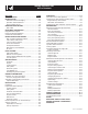
Standby Generator Sets Table of Contents INTRODUCTION .....................................................1-3 Read this Manual Thoroughly ...................................1-3 Operation and Maintenance ......................................1-3 How to Obtain Service ..............................................1-3 IDENTIFICATION RECORD .....................................2-1 Data Label ................................................................2-1 EQUIPMENT DESCRIPTION .............................
Standby Generator Sets Important Safety Instructions WARNING: GENERAL HAZARDS • For safety reasons, the manufacturer recommends that this equipment be installed, serviced and repaired by an Authorized Service Dealer or other competent, qualified electrician or installation technician who is familiar with applicable codes, standards and regulations. The operator also must comply with all such codes, standards and regulations.
Standby Generator Sets Important Safety Instructions • Generators installed with an automatic transfer switch will crank and start automatically when normal (utility) source voltage is removed or is below an acceptable preset level. To prevent such automatic start-up and possible injury to personnel, disable the generator’s automatic start circuit (battery cables, etc.) before working on or around the unit. Then, place a “Do Not Operate” tag on the generator control panel and on the transfer switch.
Standby Generator Sets Important Safety Instructions INTRODUCTION This symbol points out potential fire hazard. symbol points out potential electrical shock This hazard. Thank you for purchasing this model of the standby generator set product line. Every effort was expended to make sure that the information and instructions in this manual were both accurate and current at the time the manual was written.
Standby Generator Sets General Information IDENTIFICATION RECORD NOTE: For actual information related to this particular model, please refer to the Manual Drawing Listing located at the end of this manual, or to the data label affixed to the unit. DATA LABEL Every generator set has a DATA LABEL that contains important information pertinent to the generator.
Standby Generator Sets Equipment Description EQUIPMENT DESCRIPTION COOLANT RECOMMENDATIONS This equipment is a revolving field, alternating current generator set. It is powered by a gaseous fueled engine operating at 1800 rpm for 4-pole direct drive units, 3600 rpm for 2-pole direct drive units and 2300 - 3000 rpm for quiet drive gear units. See the Specifications section for exact numbers.
Standby Generator Sets Engine Protective Devices ENGINE PROTECTIVE DEVICES OVERCRANK SHUTDOWN The standby generator may be required to operate for long periods of time without an operator on hand to monitor such engine conditions as coolant temperature, oil pressure or rpm.
FUEL SYSTEM FUEL REQUIREMENTS The standby generator may be equipped with one of the following fuel systems: • Natural gas fuel system • Propane vapor (PV) fuel system The Manual Drawing Listing that is affixed to the unit includes the “Identification Code,” which may be used to identify the type of fuel system installed on the unit. Recommended fuels should have a Btu content of at least 1,000 Btus per cubic foot for natural gas; or at least 2,520 Btus per cubic foot for LP gas.
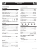
Standby Generator Sets Specifications SPECIFICATIONS COOLING SYSTEM GENERATOR Type ...................................................Pressurized Closed Recovery Water Pump.................................................................... Belt Driven Fan Speed .........................................................................2090 rpm Fan Diameter .....................................................................16 inches Fan Mode ..........................................................
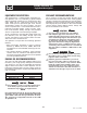
CONTROL PANEL NEUTRAL TO ALTERNATOR NEUTRAL GENERATOR CONNECTION BOX N1 N2 23 194 186 CIRCUIT BREAKER 178 GROUND FRAME RAIL Ground Level Concrete Slab STUB-UP AREA See Install Dwg for Dimensions COLD WEATHER KIT For cold climates, optional cold weather kit (part number 0F6148) is recommended. The kit includes: • Battery Warmer • 4” Junction Box with hardware • 6 qt. pack 5W-30 synthetic oil (engine) 10. Reverse the procedure to convert back to natural gas. 11.
Standby Generator Sets General Information GENERATOR AC LEAD CONNECTIONS ALTERNATOR POWER WINDING CONNECTIONS See “Voltage Codes”. This generator may be rated at any one of three voltages, either single-phase or three-phase. The electrical wires in the unit’s AC connection (lower) panel should be installed according to the number of leads and the voltage/phase required for the application. If there are any questions regarding lead connection, refer to the wiring diagrams at the back of this manual.
Standby Generator Sets Installation PRIOR TO INITIAL START-UP INSTALLATION Refer to the separate “Installation Guide QT Product Line” supplied with the unit. to initially starting the generator, it must Prior be properly prepared for use. Any attempt to PREPARATION BEFORE START-UP The instructions in this section assume that the standby generator has been properly installed, serviced, tested, adjusted and otherwise prepared for use by a competent, qualified installation contractor.
Standby Generator Sets Installation START-UP CHECKLIST • Check voltage at the generator terminals. • For 3-phase units, check phase rotation at the transfer switch terminals. The generator phase rotation must match the utility phase rotation. • Check for coolant, fuel, oil, and exhaust leaks. • Close the generators main line circuit breaker. • Turn the generator set off. • Connect the UTILITY supply to the transfer switch. • Set the AUTO/OFF/MANUAL switch to AUTO.
GENERATOR CONTROL AND OPERATION Refer to the appropriate control panel operator’s manual for this unit. OPERATING UNIT WITH MANUAL TRANSFER SWITCH If the generator was installed in conjunction with a transfer switch capable of manual operation only, the following procedure applies. A manually operated transfer switch is one that will not provide automatic start-up and does not include an intelligence circuit.
Standby Generator Sets Maintenance MAINTENANCE PERFORMED BY AUTHORIZED SERVICE FACILITIES EXHAUST MANIFOLD PROCEDURE 1. If necessary, clean gasket surfaces on exhaust manifold and cylinder head. 2. Install exhaust manifold and exhaust manifold gasket. 3. Install fasteners. NOTE: working on the generator, ensure the fol Before lowing: • The AUTO/OFF/MANUAL switch is in the OFF position. • The 15A fuse has been removed from the control box. • The 120VAC supply to the battery charger is switched OFF.
Figure 10.2 — Cylinder Head Installation CHECKING FLUID LEVELS CHECK ENGINE OIL Check engine crankcase oil level (Figure 10.3) at least every 20 hours of operation, or prior to use. • Remove oil dipstick and wipe dry with a clean, lintfree cloth. • Install oil dipstick, then remove again. • Oil should be between FULL and ADD marks. • If oil level is below the dipstick ADD mark, remove oil fill cap. Add the recommended oil to bring oil level up to the FULL mark. DO NOT FILL ABOVE THE “FULL” MARK.
Standby Generator Sets Maintenance MAINTENANCE OWNER/ OPERATOR CAN PERFORM DANGER not attempt to adjust the governor. Only Do qualified service facilities should adjust the CHECK ENGINE OIL LEVEL governor. Excessively high operating speeds are dangerous and increase the risk of personal injury. Low speeds impose a heavy load on the engine when adequate engine power is not available and may shorten engine life. Correct rated frequency and voltage are supplied only at the proper governed speed.
Standby Generator Sets Maintenance SPARK PLUGS Finally, have the insulation resistance of stator and rotor windings checked. If insulation resistances are excessively low, the generator may require drying. Reset the spark plug gap or replace the spark plugs as necessary (Figure 10.4). BATTERY 1. Clean the area around the base of the spark plugs to keep dirt and debris out of the engine. Clean by scraping or washing using a wire brush and commercial solvent. Do not blast the spark plugs to clean. 2.
Standby Generator Sets Maintenance BATTERY REPLACEMENT electrolyte fluid is an extremely corro Battery sive sulfuric acid solution that can cause severe When replacing batteries, use the same number and the type of battery that follows: burns. Do not permit fluid to contact eyes, skin, clothing, painted surfaces, etc. Wear protective goggles, protective clothing and gloves when handling a battery. If fluid is spilled, flush the affected area immediately with clear water. BCI Group No.
Standby Generator Sets Service Schedule SERVICE SCHEDULE The following is a recommended maintenance schedule for small standby and residential generator sets. The established intervals in the schedule are the maximum recommended when the unit is used in an average service application. They will need to be decreased (performed more frequently) if the unit is used in a severe application.
Standby Generator Sets Service Schedule Maintenance Tasks Level 1 Recommended to be done monthly 10 Hrs. Level 2 Task Comp. (DateInitials) Required to be done 3 months/ Break-in 30 Hrs. 1. Disable the unit from operating per the first page warning. 2. Check the engine oil level. Adjust as necessary. 3. Check the engine coolant level. Adjust as necessary. 4. Check the engine coolant thermal protection level. Correct as necessary. 5. Check the natural gas delivery system on gas engine driven units.
Standby Generator Sets Service Schedule Maintenance Tasks Level 1 RecomTask mended Comp. to be done (Datemonthly In itials) 10 Hrs. Level 2 Required to be done 3 months/ Break-in 30 Hrs. 13. Initiate an automatic start and transfer of the unit to site load and exercise it for at least 1 hour looking for leaks, loose connections or components, and abnormal operating conditions. Correct as necessary. 14.
Standby Generator Sets Troubleshooting TROUBLESHOOTING GUIDE PROBLEM CAUSE CORRECTION Engine won’t crank. 1. 15 amp fuse blown. 2. Loose or corroded or defective battery cables. 3. Defective starter contactor. 4. Defective starter motor. 5. Dead or Defective Battery. 6. 5 amp fuse blown. 1. Replace fuse. 2. Tighten, clean or replace battery cables as necessary. 3. Replace contactor.* 4. Replace starter motor.* 5. Remove, change or replace battery. 6. Replace fuse.* Engine cranks but won't start 1.
Standby Generator Sets Notes
1 2 3 4 5 6 7 8 9 10 11 12 13 14 15 16 19 20 21 049813 022097 026850 055414 022473 047411 052860 052251 052257 052252 052259 052891 0536210261 074906 025507 0F6935 046526 049814 022131 1 1 2 1 1 1 4 4 4 4 4 4 1 1 REF 1 REF REF REF NUT HEX M6 X 1.0 G8 YEL CHR WASHER LOCK M6-1/4 WASHER SHAKEPROOF EXT 1/4 STL LUG SLDLSS #2-#8 X 17/64 CU WASHER FLAT 1/4-M6 ZINC SCREW HHC M6-1.0 X 16 G8.8 NUT FLANGED HEX M12-1.75 DAMPENER VIBRATION 40 BLUE SPACER .49 X .62 X 1.
1 2 3 4 5 6 7 8 9 10 11 12 13 14 15 16 17 18 0F3408B 0F3411 025507 052647 046526 022131 050331A 050331 038805J 038804U 045771 022129 027482 0F3976 0C2454 022145 077483 0742600131 1 1 REF REF REF REF REF REF 1 1 REF REF REF 3 4 REF REF 1 BATTERY TRAY C1 CPL STRAP BATTERY RETAINMENT WASHER SHAKEPROOF EXT 7/16 STL SCREW SHC M10-1.5 X 25 G12.9 WASHER LOCK M10 WASHER FLAT 3/8-M10 ZINC BATT POST COVER RED + BATT POST COVER BLK CABLE BATTERY BLK #1 X 30.00 CABLE BATTERY RED #1 X 28.00 NUT HEX M8-1.
1 2 3 4 5 6 7 8 9 10 11 12 ** 13 14 15 16 17 18 19 20 21 22 23 24 0F7003 (XX) 0F7004 (XX) 0F7008 (XX) 0F7005 (XX) 0F7007 (XX) 0F7006 (XX) 0C2634A 0912970091 0912970090 0E5968 0E3257 077992 0F5049 0F5048 022473 022097 022127 0C2454 078115 0F3890B 0F3890 0F7365 0F7365B 0F7365A 1 1 1 1 2 1 1 1 2 1 6 18 3 3 1 1 1 24 20 2 4 2 1 1 ROOF C1 CPL CORNER POST LH SIDE C1 CPL DOOR REAR C1 CPL CORNER POST RH SIDE C1 CPL DOOR LH & RH SIDE C1 CPL DUCT FRONT DISCHARGE C1 CPL ASSEMBLY COVER ACCESS ASSY WIRE 14AWG 13.
1 2 3 4 5 6 7 8 9 10 11 12 13 14 15 16 17 18 19 20 21 22 0F7366 0F7647 0F8095 0F7172 0E3257 0F7382 0C6119 036434 036449 022129 022259 038750 044149 0E0170A 0E8816 022131 085917 0D2611 0F7644 049813 022473 022097 1 1 1 1 4 1 1 2 2 6 4 3 1 1 1 2 2 2 2 1 6 1 MUFFLER C1 MUFFLER SADDLE PIPE EXHAUST OUTLET PIPE EXH INLET MFLR SIDE 2.5L SCREW HWHTF M6-1.0 X 16 PIPE EXH INLET MANIFLD SIDE 2.5 BOLT U 5/16-18 X 2-1/4 BOLT U 5/16-18 X 2.09 SADDLE 2 INCH WASHER LOCK M8-5/16 NUT HEX 5/16-18 STEEL SCREW HHC M6-1.
Standby Generator Sets Warranty GENERAC POWER SYSTEMS STANDARD LIMITED WARRANTY FOR HOME STANDBY/LIGHT COMMERCIAL PRODUCT 45kW AND BELOW For a period of two (2) years from the date of sale, or start-up by Authorized/Certified Generac Power Systems Dealer, or branch thereof, Generac Power Systems, Inc.