Owner’s Manual Liquid-cooled, Prepackaged Standby Generators Model Number: 004988-4 27kW NG, 30kW LP Vapor This manual should remain with the unit.
INTRODUCTION Thank you for purchasing this model of the standby generator set. Every effort was expended to make sure that the information and instructions in this manual are both accurate and current at the time the manual was written. However, the manufacturer reserves the right to change, alter or otherwise improve this product(s) at any time without prior notice.
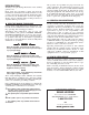
Table of Contents Liquid-cooled 30 kW Generators INTRODUCTION ............................................... IFC Section 3 — OPERATION ................................ 12 3.1 SAFETY RULES ....................................................2 Using a Standard “GTS” Transfer Switch ...........12 3.2 Control Console Components..............................13 Section 1 — GENERAL INFORMATION ............. 4 3.3 Manual Transfer and Startup ..............................14 1.1 Generator ...............
IMPORTANT SAFETY INSTRUCTIONS Liquid-cooled 30 kW Generators SAVE THESE INSTRUCTIONS – The manufacturer suggests that these rules for safe operation be copied and posted in potential hazard areas. Safety should be stressed to all operators, potential operators, and service and repair technicians for this equipment. followed during installation and maintenance of the generator and batteries.
IMPORTANT SAFETY INSTRUCTIONS Liquid-cooled 30 kW Generators • Inspect the generator regularly, and promptly repair or replace all worn, damaged or defective parts using only factory-approved parts. • Before performing any maintenance on the generator, disconnect its battery cables to prevent accidental start-up. Disconnect the cable from the battery post indicated by a NEGATIVE, NEG or (–) first. Reconnect that cable last. • Never use the generator or any of its parts as a step.
Section 1 - General Information Liquid-cooled 30 kW Generators 1.1 GENERATOR 1.3 This equipment is a liquid-cooled, engine-driven generator set. The generator is designed to supply electrical power that operates critical electrical loads during utility power failure. The unit has been factory-installed in a weather resistant, all metal enclosure and is intended for outdoor installation only. Use this generator as a source of electrical power for the operation of 120 and/or 240VAC, single-phase loads.
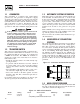
Section 1 - General Information Liquid-cooled 30 kW Generators 1.6 GENERATOR FUEL SYSTEM Figure 1.4 - Low Oil Pressure Switch The unit has been factory tested and adjusted using a natural gas fuel system. If propane (LP) gas is necessary, contact an authorized service dealer. Fuel pressure for a natural gas set up should be five inches to 14 inches of water column (0.18 to 0.5 psi) at all load ranges. Fuel pressure for an LP vapor set up should be 11 inches to 14 inches of water column (0.4 to 0.
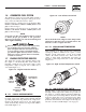
Section 1 — General Information Liquid-cooled 30 kW Generators Figure 1.6 - Low Coolant Level Sensor 1.7.7 LOW BATTERY The engine control board continually monitors the battery voltage and turns on the low battery LED if the battery voltage falls below 11.0 VDC for one minute. Low battery voltage is a non-latching alarm, which will automatically clear if the battery voltage rises above 11.0 VDC.
Section 1 — General Information Liquid-cooled 30 kW Generators 1.10 SPECIFICATIONS Fuel pressure for a natural gas set up should be five inches to 14 inches of water column (0.18 to 0.5 psi) at all load ranges. 1.10.1 GENERATOR SPECIFICATIONS Single-phase Model Rated Max. Cont. AC Power Output (kW) Rated voltage (volts) No.
Section 2 — Installation Liquid-cooled 30 kW Generators 1.13 TORQUE SPECIFICATIONS Cylinder Head ............................................ 15 (+ 90° + 90°) ft.lb. Intake Manifold ................................................................ 13 ft.lb. Exhaust Manifold ............................................................. 13 ft.lb. 1.14 ENGINE OIL RECOMMENDATIONS The unit has been filled with 5W-20 engine oil at the factory.
Section 2 — Installation Liquid-cooled 30 kW Generators • NFPA No. 37, STATIONARY COMBUSTION ENGINES AND GAS TURBINES. • NFPA No. 76A, ESSENTIAL ELECTRICAL SYSTEMS FOR HEALTH CARE FACILITIES. • NFPA No. 220, STANDARD TYPES OF BUILDING CONSTRUCTION • NFPA No. 68, GUIDE FOR EXPLOSION VENTING • NFPA No. 70, NATIONAL ELECTRICAL CODE. • NFPA No. 30, FLAMMABLE AND COMBUSTIBLE LIQUIDS CODE. • NFPA No. 10, INSTALLATION, MAINTENANCE AND USE OF PORTABLE FIRE EXTINGUISHERS. 2.1.
Section 2 — Installation Liquid-cooled 30 kW Generators 2.5 EMERGENCY CIRCUIT ISOLATION METHOD Figure 2.2 – Generator Grounding Lug (typical) This prevents overloading the generator by keeping electrical loads below the wattage/amperage capacity of the generator. If the generator can only power critical loads, within it’s wattage/amperage capacity, during utility power outages, use the emergency circuit isolation method.
Section 2 — Installation Liquid-cooled 30 kW Generators Control system interconnections consist of N1 and N2, and leads 23 and 194. Control system interconnection leads must be run in a conduit that is separate from the AC power lead. Recommended wire gauge sizes for this wiring depends on the length of the wire, as recommended below: MAXIMUM WIRE LENGTH 460 feet (140m) 461 to 730 feet (223m) 731 to 1,160 feet (354m) 1,161 to 1,850 feet (565m) RECOMMENDED WIRE SIZE No. 18 AWG. No. 16 AWG. No. 14 AWG. No.
Section 3 — Operation Liquid-cooled 30 kW Generators 2.11.1 PRIOR TO INITIAL START-UP 2.11.6 BELT TENSION to initially starting the generator, it must Prior be properly prepared for use. Any attempt to Check-the engine-fan belt tension and condition prior to placing the unit into service and at recommended intervals. Belt tension is correct when a force of approximately 22 pounds (10 kg), applied midway between pulleys, deflects the belt about 3/8- to 5/8inch (10 to 16 mm).
Section 3 - Operation Liquid-cooled 30 kW Generators MANUAL — The control board will start and run the generator whenever the switch is in the manual position. AUTO — The control board will monitor the twowire start circuit. When a two-wire start is issued the control board will immediately start and run the generator. Whe the two-wire start is removed the control board will immediately stop the generator.
Section 3 — Operation Liquid-cooled 30 kW Generators The system ready LED will be OFF when the switch is in the manual or OFF positions. Figure 3.2 — Engine Governor Adjustment The system ready LED is also used to indicate the presence of utility sensing at the PCB when the switch is either in the AUTO or MANUAL modes. The LED will flash at the rate of 1/2 second on, 1/2 second off if the utility sensing level is below the transfer back threshold.
Section 4 — Maintenance Liquid-cooled 30 kW Generators 3.7 WEEKLY EXERCISE CYCLE 4.1 The engine control board will start and run the generator once every seven days for approximately 12 minutes. If utility should fail during this exercise period, the engine control board will transfer the load to the generator output and continue to run until utility returns. On the day, and at the time of day chosen for the generator to exercise, set the weekly exercise cycle as follows: 1.
Section 4 — Maintenance Liquid-cooled 30 kW Generators 4.3 OVERLOAD PROTECTION FOR ENGINE DC ELECTRICAL SYSTEM Engine cranking, start up and running are controlled by a solid state Engine Controller circuit board. Battery voltage is delivered to that circuit board via a 15 amp fuse. These overcurrent protection devices will open if the circuit is overloaded. a circuit breaker opens or a fuse element Ifmelts, find the cause of the overload before resetting the circuit breaker or replacing the fuse. 4.
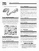
Section 4 — Maintenance Liquid-cooled 30 kW Generators 4.5.8 CHECK FAN BELT Figure 4.2 - Oil Filter • Inspect fan belts every three months. Replace any damaged, deteriorated, worn or otherwise defective belt. • Check fan belt tension. Thumb pressure, exerted midway between pulleys, should deflect about 3/8 to 5/8 inch. Adjust belt tension as required. 4.5.9 INSPECT ENGINE GOVERNOR Visually inspect electronic governor. DANGER not attempt to adjust the governor.
Section 4 — Maintenance Liquid-cooled 30 kW Generators 4.5.12 SPARK PLUGS Reset the spark plug gap or replace the spark plugs as necessary. See Section 6. 1. Clean the area around the base of the spark plugs to keep dirt and debris out of the engine. Clean by scraping or washing using a wire brush and commercial solvent. Do not blast the spark plugs to clean. 2. Remove the spark plugs and check the condition. Replace the spark plugs if worn or if reuse is questionable.
Section 4 — Maintenance Liquid-cooled 30 kW Generators DANGER Storage batteries give off explosive hydrogen gas. This gas can form an explosive mixture around the battery for several hours after charging. The slightest spark can ignite the gas and cause an explosion. Such an explosion can shatter the battery and cause blindness or other injury. Any area that houses a storage battery must be properly ventilated.
Section 4 — Maintenance Liquid-cooled 30 kW Generators 4.7 SCHEDULED MAINTENANCE The following is a recommended maintenance schedule for small standby and residential generator sets. The established intervals in the schedule are the maximum recommended when the unit is used in an average service application. They will need to be decreased (performed more frequently) if the unit is used in a severe application.
Section 4 — Maintenance Liquid-cooled 30 kW Generators Maintenance Tasks Level 1 Recommended to be done monthly/ 10 hrs. Level 2 Task Comp. (DateInitials) Required to be done 3 months/ Break-in 30 hrs. Level 3 Task Comp. (DateInitials) Required to be done Semiannually/ 50 hrs. Level 4 Task Comp. (DateInitials) Required to be done Annually/ 100 hrs. Task Comp. (DateInitials) 1. Disable the unit from operating per the first page warning. 2. Check the engine oil level. Adjust as necessary. 3.
Section 4 — Maintenance Liquid-cooled 30 kW Generators Maintenance Tasks 13. Initiate an automatic start and transfer of the unit to site load and exercise it for at least 1 hour looking for leaks, loose connections or components, and abnormal operating conditions. Correct as necessary. 14. Start and exercise the unit at full rated load (use a load bank if the site load is not enough) for at least 2 hours looking for leaks, loose connections or components, and abnormal operating conditions.
Section 5 — Troubleshooting Liquid-cooled 30 kW Generators TROUBLESHOOTING POINTS PROBLEM CAUSE CORRECTION Engine won’t crank. 1. 15 amp fuse blown. 2. Loose or corroded or defective battery cables. 3. Defective starter contactor. 4. Defective starter motor. 5. Dead or Defective Battery. 6. 4 amp fuse blown. 1. Replace fuse. 2. Tighten, clean or replace battery cables as necessary. 3. Replace contactor. 4. Replace starter motor. 5. Remove, change or replace battery. 6. Replace fuse.
Section 6 - Notes Liquid-cooled 30 kW Generators 24
Section 7 — Installation Diagram Liquid-cooled 30 kW Generators Installation Diagram — Drawing No.
Section 8 - Electrical Data Liquid-cooled 30 kW Generators Wiring Diagram — Engine — Drawing No.
Section 8 - Electrical Data Liquid-cooled 30 kW Generators Wiring Diagram — Engine — Drawing No.
Section 8 - Electrical Data Liquid-cooled 30 kW Generators Electrical Schematic — Engine — Drawing No. 0E6200-B ALTERNATOR ROTOR ALTERNATOR STATOR AUTOMATIC VOLTAGE REGULATOR BRUSH ASSEMLY (GENERATOR) BATTERY CHARGER BATTERY CHARGE WINDING CIRCUIT BREAKER (OUTPUT) CIRCUIT BREAKER (EXCITATION) DIODE [FIELD BOOST] DISPLACED PHASE EXCITATION LEGEND {CONT.]: F1 FUSE, BAT. POWER (15A AGC TYPE) F2 FUSE, B/C (4A AGC TYPE) ICT TERMINAL BLOCK, INTERCONNECT.
Section 8 - Electrical Data Liquid-cooled 30 kW Generators Electrical Schematic — Engine — Drawing No.
16 30 7 6 5 2 4 3 ENGINE FOOT 12 13 17 9 35 18 16 8 40 39 36 30 16 43 44 TO ENGINE BLOCK 34 35 41 38 18 44 32 33 22 42 20 31 21 20 7 6 5 37 1 13 MOUNTING BASE 15 14 12 11 REAR BEARING CARRIER HARNESS WIRE TO STARTER CONTACTOR TO STARTER BOLT TO ENGINE 18 BLOCK 14 16 10 4 3 2 Section 9 - Exploded Views and Parts Liquid-cooled 30 kW Generators Mounting Base — Drawing No.
Section 9 - Exploded Views and Parts Liquid-cooled 30 kW Generators Mounting Base — Drawing No. 0E6266-F ITEM 1 2 3 4 5 6 7 8 9 10 11 12 13 14 15 16 17 18 20 21 22 23 * 24 * 25 * 26 * 30 31 32 33 34 35 36 37 38 39 40 41 42 43 44 PART NO.
32 3 30 31 LATCH DETAIL 38 32 4 34 18 17 43 27 2 40 4 37 35 25 RADIATOR SUPPORT 49 4 33 4 STATES FOAM IS ON FAR SIDE STATES FOAM IS ON NEAR SIDE 4477 49 25 4 4 4 13 11 9 SEE LATCH DETAIL 26 4444 TO "A" TYPICAL OF ROOF PANEL THAT REQUIRE INSULATION. SECURE AS SHOWN.
Section 9 - Exploded Views and Parts Liquid-cooled 30 kW Generators Enclosure — Drawing No. 0F1142-B ITEM 1 2 3 4 5 6 7 8 9 10 11 12 13 14 15 16 17 18 19 20 21 22 23 24 25 26 27 28 29 30 31 32 33 34 35 36 37 38 39 40 41 42 43 44 45 46 47 48 49 50 * 51 52 53 PART NO.
Section 9 - Exploded Views and Parts Liquid-cooled 30 kW Generators Control Panel — Drawing No.
Section 9 - Exploded Views and Parts Liquid-cooled 30 kW Generators Control Panel — Drawing No. 0E7118-K ITEM PART NO. QTY. 1 2 3 4 5 6 7 8 9 10 11 12 13 14 15 16 17 18 19 20 21 0E7195 0E7196 0E7197 0E7193 0E7194 0E4494 082573 032300 022676 067682B 060015 054199 0C2657 099076 040213 0E9668 067680 0E6875A 0E6881 * 0C5139 * 0C5142 * 1 1 1 1 1 1 1 2 1 1 1 1 1 1 2 1 1 1 REF. REF. REF.
36 50 24 2 25 58 43 55 57 25 54 53 42 61 60 38 61 24 53 60 14 85 36 35 39 51 58 57 30 69 31 87 39 GROUND WIRE 32 86 36 35 39 35 68 65 79 17 66 67 REMOVE & REPLACE 1 49 78 46 21 20 46 84 43 42 49 42 16 63 38 64 88 18 47 47 4 15 47 43 2 19 80 81 26 42 38 42 81 6 48 7 36 43 3 5 42 44 36 35 89 28 27 40 33 34 82 41 47 45 83 74 34 31 72 32 12 36 35 38 10 29 42 BAFFLE REAR UPPER 37 42 8 35 84 30 73 11 Secti
Section 9 - Exploded Views and Parts Liquid-cooled 30 kW Generators Engine — Drawing No. 0F6836-B ITEM PART NO. QTY.
38 FRAME 9 8 3 11 10 9 25 26 12 "A" 27 20 15 1 4 21 3 12 TO WATER PUMP 22 24 24 23 6 2 17 12 7 12 15 28 5 32 13 31 18 12 14 33 TO "A" 29 35 30 12 TO THERMOSTAT HOUSING TO ENGINE Section 9 - Exploded Views and Parts Liquid-cooled 30 kW Generators Radiator — Drawing No.
Section 9 - Exploded Views and Parts Liquid-cooled 30 kW Generators Radiator — Drawing No. 0F6848-B ITEM 1 2 3 4 5 6 7 8 9 10 11 12 13 14 15 17 18 20 21 22 23 24 25 26 27 28 29 30 31 32 33 35 PART NO. 0E9947 0E6340 0E8531 0E6398 0F6630 080713 076749 049814 022131 046526 045772 035685 0E8562 058443 0C2454 048031C 029032 046627 069811 065852 0A2111 052250 035461 0C7649 069860C 0F6746 0F6631 0F6657 055934N 092079 022097 047411 QTY.
Section 9 - Exploded Views and Parts 42 43 41 15 "B" 28 21 8 40 5 16 2 4 10 29 32 30 29 11 17 6 1 7 9 13 31 29 12 6 3 34 33 14 TO AIR CLEANER 13 TO "B" 18 26 27 19 28 26 25 20 40 39 Liquid-cooled 30 kW Generators Fuel System — Drawing No.
Section 9 - Exploded Views and Parts Liquid-cooled 30 kW Generators Fuel System — Drawing No. 0F6849-A ITEM PART NO.
Section 9 - Exploded Views and Parts 12 8 7 5 18 42 LOCKTIGHT 15 7 17 1 4 16 31 30 LEADS 2 6 9 21 13 LOCKTIGHT 3 10 11 20 19 14 Liquid-cooled 30 kW Generators Alternator — Drawing No.
Section 9 - Exploded Views and Parts Liquid-cooled 30 kW Generators Alternator — Drawing No. 0F5092-B ITEM PART NO. QTY.
Section 9 - Exploded Views and Parts Liquid-cooled 30 kW Generators Exhaust — Drawing No. 0F0968-B 21 13 2 11 18 1 19 17 16 7 8 16 16 17 6 18 TO MANIFOLD 19 8 TO COMPARTMENT 10 15 20 16 17 3 10 20 17 5 9 TO MANIFOLD 12 13 14 3 4 12 ITEM PART NO. QTY. 1 2 3 4 5 6 7 0F0738 0F6258 044149 0F1008 0F1009 039288 0E5914 1 1 2 1 1 1 1 8 9 10 11 0E8726 0E0170 036797 080762 2 2 2 1 44 DESCRIPTION MUFFLER 7"X9"-(2)2"IN/2.5"OUT PIPE MUFFLER OUT GASKET EXHAUST RING EXHAUST PIPE LH 3.
Section 9 - Exploded Views and Parts Liquid-cooled 30 kW Generators Air Cleaner — Drawing No. 0F6850-A 1 2 3 4 5 6 7 8 9 ITEM 1 2 3 4 5 6 7 8 9 PART NO. 0E5193 0E0519A 049226 049815 0C8127 022127 062974 0A5547 037561 QTY. 1 1 4 4 1 1 1 1 1 DESCRIPTION PLATE AIR CLEANER ADAPTER ADAPTER CARBURETOR W/PVC CONN WASHER LOCK M5 SCREW HHC M5-0.8 X 16 G8.
Section 10 – Warranty Liquid-cooled 30 kW Generators GENERAC POWER SYSTEMS "TWO YEAR" LIMITED WARRANTY FOR GUARDIAN® "PREPACKAGED EMERGENCY AUTOMATIC STANDBY GENERATORS" For a period of two years from the date of original sale, Generac Power Systems, Inc. (Generac) warrants that its Guardian generator will be free from defects in material and workmanship for the items and period set forth below.