
User manual

26
2.3 COOLING AND VENTILATING AIR
It is absolutely essential that an adequate flow of
air for cooling, ventilating and engine combustion
be supplied to the generator set. Without sufficient
airflow, the engine/generator quickly overheats. Such
overheating can cause serious operating difficulties
and also may cause fire and personal injury. The
installer must make sure that sufficient air is avail-
able to the generator for cooling, ventilating and
combustion. The installer also must provide for a
path for exhausting the cooling air to the exterior of a
compartment, if so equipped.
DANGER
Never use discharged cooling air for heating or
permit such air to enter the vehicle interior. This
air contains deadly carbon monoxide gas and
other poisonous, flammable or explosive gases.
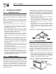
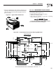
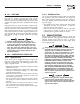
2.3.1 GENERATOR AIRFLOW
Engine operation drives cooling fans for the two-stage
cooling air system. A pressure fan draws cooling air
into the bottom right side of the generator (Figure 2.9).
This airflow cools the engine/generator and electronic
components. The second part of the cooling system, a
suction fan, draws air that is heated from a hot engine
into a collector compartment at the left side of the unit.
This heated air (although cooler than exhaust muffler)
is then deflected out the bottom toward the ground.
Figure 2.9 – Airflow Through Engine/Generator
2.3.2 TESTING THE INSTALLATION
The manufacturer recommends testing the installa-
tion to be sure adequate cooling airflow is available to
the unit before placing the unit into service. If the unit
shows signs of overheating, enlarge the air openings.
Never place a unit into service until absolutely certain
that cooling and ventilation is adequate.
NOTE:
Test the installation, especially if bringing in air
from below the generator set.
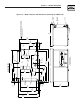
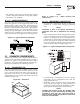
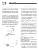
2.4 GASOLINE FUEL SYSTEM
The installation of a gasoline fuel system (Figure
2.10) for a recreational vehicle generator set must
comply with applicable codes, standards and regula-
tions. The entire fuel system must be completely free
of leaks. There must be no possibility of gasoline
vapors entering the vehicle interior.
Figure 2.10 – Generator Fuel System
GENERAC OHVI INDUSTRIAL ENGINE
I
t
r
e
,
e
h
i
t
w
a
n
c
.
-
s
m
,
I
e
W
POWERED
W
y
s
S
r
o
P
w
e
A
C
N
R
E
G
E
OHVI
t
GENERAC
TM
RV SERVICE LOCATOR:
1.800.333.1322
QUIETPACT 40G
*
SERVICE ACCESS PANEL
OIL LEVEL: CHECK DAILY
AIR FILTER: CLEAN PREFILTER
EVERY 100 HOURS.
REPLACE ELEMENT
EVERY 250 HOURS.
OIL & OIL FILTER:
CHANGE EVERY 100
(IF NECESSARY)
EVERY 500 HOURS.
HOURS. REPLACE PLUGS
PLUGS EVERY 100
INSPECT & CLEANSPARK PLUGS:
REPLACEMENT INFORMATION
*
PERFORM MORE OFTEN IN DUSTY CONDITIONS
AIR FILTER LOCATED BEHIND PANEL.
MAINTENANCE SCHEDULE
AIR FILTER P/N: 0D3262
070185OIL FILTER P/N:
SPARK PLUG P/N: 072347
OIL CAPACITY WITH FILTER:
0.8L/0.84QT
TEMPERATURE SAE VISCOSITY
32˚F AND HIGHER
10˚F TO 100˚F
0˚F TO 80˚F
-20˚F TO 50˚F 5W-30
10W-30
15W-40
30
WHEN SERVICE OR PARTS ARE NEEDED IN
THE USA OR CANADA, CONTACT THE GENERAC
SERVICE LOCATOR AT 1-800-333-1322.
HOURS. (OR ANNUALLY)
PREFILTER P/N: 0D4511
FUEL FILTER P/N: 0D7515
FUEL FILTER: CHANGE EVERY 400
HOURS. (OR ANNUALLY)
*
*
PRIME
FUEL
STOP
START
30A
C.B.
A
FUSE
CONTROL CENTER
7.5
T
o
R
e
m
o
v
e
Fuel Pump & Fuel Filter
(Behind Access Panel & Air Filter)
DANGER
Gasoline is highly flammable, and its vapors are
explosive. Comply with all codes, standards and
regulations pertaining to gasoline fuel systems
used in recreational vehicle generators. Properly
install and maintain the fuel system and keep it
entirely free of leaks. Gasoline vapors must not
enter the vehicle interior.
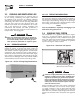
Factory installed generator fuel system components
include (a) fuel filter, (b) 12-volt DC electric pump,
(c) engine carburetor, and (d) interconnecting lines
and fittings. Connect a fuel supply line to the fuel
filter inlet. Use a flexible length of approved fuel hose
between the fuel filter inlet connection and rigid fuel
lines.
Section 2 – Installation
Recreational Vehicle Generator