Owner’s Manual and Installation Instructions Air-cooled Recreational Vehicle Generators • Model: 004700-0 QUIETPACT 40G This manual should remain with the unit.
INTRODUCTION Thank you for purchasing this model of the QUIETPACT product line by Generac Power Systems Inc. This model is designed and manufactured to supply electrical power for recreational vehicles. READ THIS MANUAL THOROUGHLY If any portion of this manual is not understood, contact the nearest Authorized Service Dealer for starting, operating and servicing procedures.
Table of Contents Recreational Vehicle Generator Part I – Owner’s Manual Introduction ...................................... Inside Front Cover Read This Manual Thoroughly ................................IFC Contents .................................................................IFC Operation and Maintenance ....................................IFC How to Obtain Service ............................................IFC Authorized Service Dealer Locator Number ..............
Safety Rules Recreational Vehicle Generator SAVE THESE INSTRUCTIONS – The manufacturer suggests that these rules for safe operation be copied and posted in potential hazard areas of the recreational vehicle. Safety should be stressed to all operators and potential operators of this equipment. WARNING: The engine exhaust from this product contains chemicals known to the state of California to cause cancer, birth defects or other reproductive harm.
Safety Rules Recreational Vehicle Generator • When working on this equipment, remain alert at all times. Never work on the equipment when physically or mentally fatigued. • Inspect the generator regularly, and contact the nearest Authorized Service Dealer immediately for parts needing repair or replacement. • Before performing any maintenance on the generator, disconnect its battery cables to prevent accidental start up. Disconnect the cable from the battery post indicated by a NEGATIVE, NEG or (–) first.
Section 1 – General Information Recreational Vehicle Generator 1.1 GENERATOR IDENTIFICATION Please record the following information from the generator DATA DECAL or information decal. 1. Model Number _____________________ 2. Serial Number __________________ 3. kW Rating _________________________ 4. Rated Voltage __________________ Model: 004700-0 1. 2. 3. 4. 5. 6. 7. 8. 9. 10.
Section 1 – General Information Recreational Vehicle Generator 1.2 GENERATOR APPLICABILITY These generators have been designed and manufactured for supplying electrical power for recreational vehicles. Do not modify the generator or use it for any application other than for what it was designed. If there are any questions pertaining to its application, contact an Authorized Service Dealer. Do not use the unit until advised by a competent authority.
Section 1 – General Information Recreational Vehicle Generator 1.5.5 GENERATOR The manufacturer does not recommend using any gasoline containing alcohol (such as “gasohol”). If using any gasoline containing alcohol, it must not contain more than 10 percent ethanol, and it must be removed from the generator during storage. Do NOT use any gasoline containing methanol. If using gasoline with alcohol, inspect more frequently for fuel leaks and other abnormalities. 1.5.
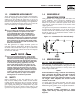
Section 2 – Operation Recreational Vehicle Generator 2.1 GENERATOR CONTROL PANEL The following features are mounted on the generator control panel (Figure 2.1): Figure 2.1 – Generator Control Panel CONTROL CENTER S T A R T F U E L S T O P P R IM E C .B . 3 0 A FUS E 7. 5 A 2.2 OPTIONAL REMOTE START/STOP PANEL A remote mounted Start/Stop Panel is available that allows starting and stopping the generator engine conveniently from inside the vehicle.
Section 2 – Operation Recreational Vehicle Generator 2.4.2 ENGINE LUBRICATION Have the engine crankcase properly serviced with the recommended oil before starting. Refer to Section 1.5.4, and Sections 3.1 and 3.2 for oil servicing procedures and recommendations. attempt to crank or start the engine before Any it has been properly serviced with the recommended oil may result in an engine failure. 2.4.3 FUEL SUPPLY The engine must have an adequate supply of proper fuel to operate.
Section 2 – Operation Recreational Vehicle Generator 2.6 STOPPING THE GENERATOR 1. Turn OFF all electrical loads using the means provided (such as a main circuit breaker or transfer switch). 2. Let generator run at no-load for a few minutes, to stabilize internal engine generator temperatures. 3. Place the Start/Stop switch in its STOP position. 2.
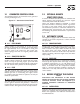
Section 2 – Operation Recreational Vehicle Generator 2.9.3 FIELD BOOST The Controller Circuit Board houses a field boost diode and resistor that are not part of the automatic choke circuit. These two components are part of a “field boost” circuit (Figure 2.3). During engine cranking only, a positive DC (battery) voltage is delivered through the diode, resistor, brushes and slip rings, to the generator rotor. Application of this voltage to the rotor “flashes the field” whenever it is started.
Section 3 – Maintenance Recreational Vehicle Generator 2.10.4 OPERATION IN HIGH GRASS OR BRUSH 3.1 Never operate the generator while the vehicle is parked over high grass, weeds, brush, leaves or any other combustible substance. Such materials can ignite and burn from the heat of the exhaust system. The generator exhaust system becomes extremely hot during operation and remains hot for a long time after it has shut down. For oil capacities and requirements, see “Engine Oil Requirements,” Section 1.5.
Section 3 – Maintenance Recreational Vehicle Generator • Change the engine oil filter after the first 25 hours of operation, and every 100 operating hours thereafter. To change the oil and/or oil filter, proceed as follows (see Figure 3.1): 1. Run the engine until it is thoroughly warmed up (at least five minutes) then shut OFF the engine. 2. Immediately after the engine shuts OFF, pull the oil drain cover free of the base.
Section 3 – Maintenance Recreational Vehicle Generator 3.4 CLEAN AIR INTAKE Clean all foreign material from the air intake (Figure 3.3) at least once every 100 hours of operation. Clean more often if necessary. Inspect the area around the generator exhaust muffler periodically and remove all grass, leaves, dirt, etc., from this area. 3.6 FUEL FILTER Remove and replace the fuel filter (Figure 3.5) once each year or every 400 hours of operation, whichever comes first.
Section 3 – Maintenance Recreational Vehicle Generator 3.8 CLEANING THE GENERATOR Keep the generator set as clean and dry as possible. Protect the unit against excessive dust, dirt, corrosive vapors, road splash, etc. Permitting dirt and moisture to accumulate on generator windings will have an adverse effect on the insulation resistance of those windings. When moisture is allowed to remain in contact with windings, some of the moisture will be retained in voids and cracks in the insulation.
Section 3 – Maintenance Recreational Vehicle Generator 3.10 MAJOR SERVICE MANUAL To obtain a service manual for the generator, contact the nearest Authorized Service Dealer. Make sure to identify the MODEL NUMBER and SERIES. 3.11 EXERCISING THE GENERATOR The manufacturer recommends that the generator be started and operated at least once every seven days. Let the unit run for at least 30 minutes to “exercise” the engine. 3.12 OUT OF SERVICE PROCEDURE 3.12.
Section 3 – Maintenance Recreational Vehicle Generator 2. When valve clearance is correct, hold the pivot ball stud with the allen wrench and tighten the rocker arm jam nut with a crows foot. Tighten the jam nut to 65-85 inch-pounds torque. After tightening the jam nut, recheck valve clearance to make sure it did not change (Figure 3.8). Figure 3.8 — Tightening Jam Nut 16 3.14 RV GENERATOR SERVICE INTERVAL 50 Hours ................................ Clean Spark Arrestor 100 Hours .........................
PART II – INSTALLATION INSTRUCTIONS DANGER ONLY QUALIFIED ELECTRICIANS OR CONTRACTORS SHOULD ATTEMPT INSTALLATION!!
Safety Rules Recreational Vehicle Generator DANGER: For fire safety, installation of a generator into a recreational vehicle must comply strictly with article 551, NFPA 70; ANSI C1-1975; AND, ANSI A119.2-1975/NFPA 501C “Standard for Recreational Vehicles” (Part 3, “Installation of Electrical Systems”). In addition, installation must comply with the manufacturer’s instructions and recommendations.
Safety Rules Recreational Vehicle Generator ELECTRICAL HAZARDS FIRE HAZARDS • The generator covered by this manual produces dangerous electrical voltages and can cause fatal electrical shock. Avoid contact with bare wires, terminals, connections, etc., while the unit is running. Ensure all appropriate covers, guards and barriers are in place before operating the generator. If work must be done around an operating unit, stand on an insulated, dry surface to reduce shock hazard.
Section 1 – General Information Recreational Vehicle Generator 1.1 PURPOSE AND SCOPE OF THE MANUAL These Installation Instructions have been prepared especially for the purpose of familiarizing installers and owners of the applicable equipment with the product's installation requirements. Give serious consideration to all information and instructions in the manual, both for safety and for continued reliable operation of the equipment.
476.4 [ 18 3/4"] 376.5 [ 14 13/16"] 55.5 [ 2 3/16"] 429.5 [ 16 15/16"] TAIL PIPE EXIT 342.2 [ 13 1/2"] 29 [ 1 1/8"] 48.1 [ 1 7/8"] 416 [ 16 3/8"] HOT AIR EXHAUST TYP. 6.7 [ 1/4"] 222.7 [ 8 3/4"] 50.8 [2"] 210 [ 8 1/4"] 369.7 [ 14 9/16"] 343.4 [ 13 1/2"] 300.7 [ 11 13/16"] 101 [ 4"] 82.5 [ 3 1/4"] 423.2 [ 16 11/16"] 736.4 [ 29"] OIL DRAIN FRONT DOOR ACCESS FOR ALL REQUIRED MAINTENANCE REF. 749.8 [ 29 1/2"] 688.3 [ 27 1/8"] 83.5 [ 3 5/16"] 170 [ 6 11/16"] 176.
Section 2 – Installation Recreational Vehicle Generator 2.1 LOCATION AND SUPPORT 2.1.1 GENERATOR LOCATION The most desirable location for the generator set is between the vehicle's main frame members. However, this is seldom possible. Most units must be installed on the side of the vehicle and are difficult to reinforce. Many recreational vehicles have been factory equipped with an area for the generator set. Some vehicles may even have a generator compartment provided by the vehicle manufacturer.
Section 2 – Installation Recreational Vehicle Generator • The installer must make certain that the selected location will permit adequate cooling and ventilating airflow to be supplied. 2.1.4 GENERATOR RESTRAINT Use four 5/16"-18 hardened steel bolts (Grade 5) to fasten the generator to the supporting frame or the support tubing. These bolts must pass through (a) the generator mounting base, (b) the compartment floor (if a compartment is used) and (c) the supporting framework (Figure 2.3).
Section 2 – Installation Recreational Vehicle Generator • Holes and openings made in the compartment walls to allow for the passage of electrical conduit, conductors, hoses, cables, etc., into the vehicle living area must be sealed vapor tight with silicone rubber base sealant. • If flexible metal conduit is used, it must be sealed internally at the end where it terminates inside the compartment’s electrical junction box.
Section 2 – Installation Recreational Vehicle Generator • Line the compartment door interior (except for air openings) with suitable, fireproof sound insulation (such as 1-inch (25 mm) thick fiberglass with a 2pound density). 2.2.5 COMPARTMENT FLOOR CUTOUTS Provide openings in the generator compartment for the following items (Figure 1.2): • Engine exhaust and cooling air outlets • Generator cooling air inlet • Four holes for passage of generator mounting bolts. See Section 2.1.4. Figure 2.
Section 2 – Installation Recreational Vehicle Generator 2.3 COOLING AND VENTILATING AIR It is absolutely essential that an adequate flow of air for cooling, ventilating and engine combustion be supplied to the generator set. Without sufficient airflow, the engine/generator quickly overheats. Such overheating can cause serious operating difficulties and also may cause fire and personal injury.
Section 2 – Installation Recreational Vehicle Generator 2.4.1 FUEL TANK 2.4.2.2 Flexible Fuel Line Either the generator must share the vehicle engine's fuel tank, or install a separate fuel tank for the generator set. All fuel tanks installed on the vehicle must be constructed, installed and restrained so they comply with applicable codes, standards and regulations. Use an approved flexible length of fuel hose between the generator fuel inlet connection and rigid fuel lines.
Section 2 – Installation Recreational Vehicle Generator 2.5.1 SPARK ARRESTOR 2.5.2 EXHAUST SYSTEM SAFETY This spark arrestor assembly meets code and standard requirements of the U.S. Forest Service. Use only mufflers and parts approved by the manufacturer.
Section 2 – Installation Recreational Vehicle Generator • Wiring must be of adequate size, have approved insulative qualities and be properly supported. • Conduit and wire openings into the generator compartment (if used) must be vapor-sealed to prevent entry of flammable, explosive or poisonous gases into the vehicle. Figure 2.13 – Generator AC Output Leads 483.1 REMOTE PANEL CONNECTOR 2.6.
Section 2 – Installation Recreational Vehicle Generator 2.6.5 ISOLATING DIFFERENT POWER SOURCES Connections from the junction box must terminate in a double-pole, double-throw transfer switch (Figure 2.14). An alternate method for isolating different power sources is by using an isolating receptacle (Figure 2.15). Whichever method is used, be certain that both power sources are NOT connected at the same time. 2.6.
Section 2 – Installation Recreational Vehicle Generator 2.6.7 GROUND FAULT CIRCUIT INTERRUPTERS The National Electrical Code (NFPA 70, 551-7) requires that ground fault circuit interrupters (GFCIs) be installed on all external and some internal electrical receptacles. Contact the dealer for recommendations. 2. Connect the battery cable from the battery post indicated by a NEGATIVE, NEG or (-) to the frame ground connection (Figure 2.16). 3. Connect cables so the connectors are clean and tight.
Section 3 – Post-Installation Start-up Adjustments Recreational Vehicle Generator 2.8.1 REMOTE START/STOP PANEL 3.3 A remote mounted Start/Stop panel (Figure 2.18) is available that allows the user to start and stop the generator engine conveniently from inside the vehicle. The remote panel includes a Start/Stop switch, hourmeter, generator run lamp, a fuel prime switch, and a wire harness. The hourmeter should be used in conjunction with the maintenance operations found in Part I of this manual.
Section 3 – Post-installation Start-up Adjustments Recreational Vehicle Generator 3.5 INSTALLATION CHECKLIST EXHAUST SYSTEM LOCATION AND SUPPORT ❑ Exhaust system complies with all applicable codes. ❑ Generator is properly located. ❑ Exhaust system is properly and safely installed. ❑ Generator is properly supported. ❑ Generator is properly restrained. ELECTRICAL CONNECTIONS GENERATOR COMPARTMENT ❑ Connections comply with local code requirements and all National Electrical Codes.
Appendix 1 – Notes Recreational Vehicle Generator 34
Appendix 2 – Troubleshooting Recreational Vehicle Generator TROUBLESHOOTING GUIDE Problem Cause Correction The engine will not crank. 1. Fuse blown 2. Loose, corroded or defective battery cables 3. Defective engine Start/Stop switch 4. Defective starter contactor 5. Defective starter motor 6. Low or defective battery 1. Replace fuse. 2. Tighten, clean or replace as necessary. 3. Replace Start/Stop switch. The engine cranks but will not start. 1. Out of fuel 2. Defective fuel pump 3.
Appendix 3 — Electrical Data Recreational Vehicle Generator Electrical Schematic and Wiring Diagram – Drawing No.
Appendix 3 — Electrical Data Recreational Vehicle Generator Electrical Schematic and Wiring Diagram – Drawing No.
38 41 38 21 45 4 30 5 19 59 17 55 42 2 46 37 55 32 3 50 33 34 48 9 31 55 36 58 16 40 56 21 27 28 21 35 21 55 41 43 54 23 12 10 24 TO CARB 13 51 1 21 53 18 22 21 57 21 41 39 20 21 6 42 52 15 8 47 22 23 11 21 7 24 15 25 49 21 26 14 44 Appendix 4 — Exploded Views and Parts Lists Recreational Vehicle Generator Enclosure – Drawing No.
Appendix 4 — Exploded Views and Parts Lists Recreational Vehicle Generator Enclosure – Drawing No. 0D8352-G ITEM 1 2 3 4 5 6 7 8 9 10 11 12 13 14 15 16 17 18 19 20 21 22 23 24 25 26 27 28 30 31 32 PART NO. QTY.
Appendix 4 — Exploded Views and Parts Lists 18 37 18 21 28 38 23 21 2 18 27 26 10 25 2 18 1 4 3 5 2 7 24 8 24 9 22 2 35 11 12 39 2 15 18 2 23 36 13 2 2 8 2 14 17 18 16 18 2 0 1 21 29 32 30 42 34 31 29 33 Recreational Vehicle Generator Generator – Drawing No.
Appendix 4 — Exploded Views and Parts Lists Recreational Vehicle Generator Generator – Drawing No. 0D8353-H ITEM 1 2 3 4 5 6 7 8 9 10 11 12 13 14 15 16 17 18 19 20 21 22 23 24 25 26 27 28 29 30 31 32 33 34 35 36 37 38 39 41 42 PART NO.
Appendix 4 — Exploded Views and Parts Lists Recreational Vehicle Generator Control Panel – Drawing No.
Appendix 4 — Exploded Views and Parts Lists Recreational Vehicle Generator Control Panel – Drawing No. 0D8354-E ITEM 1 2 3 4 5 6 7 8 9 10 11 12 13 14 15 16 17 18 19 20 21 22 23 24 25 26 27 28 29 30 31 32 33 34 35 36 37 38 39 PART NO.
Appendix 4 — Exploded Views and Parts Lists 33 57 30 58 6 35 53 52 43 41 42 44 55 59 60 54 45 9 39 9 38 44 61 32 29 62 26 27 22 21 23 24 25 34 20 40 14 19 13 63 8 37 31 9 28 10 11 12 36 5 4 7 56 9 9 17 16 15 15 16 3 1 2 Recreational Vehicle Generator GN-220 H/SH Engine – Drawing No.
Appendix 4 — Exploded Views and Parts Lists Recreational Vehicle Generator GN-220 H/SH Engine – Drawing No. 0D8355-S Part 1 ITEM 1 2 3 4 5 6 7 8 9 10 11 12 13 14 15 16 17 19 20 21 22 23 24 25 26 27 28 29 30 31 32 33 34 35 36 37 38 39 40 41 42 43 44 45 52 53 54 55 56 57 58 59 60 61 62 63 PART NO.
Appendix 4 — Exploded Views and Parts Lists 47 13 11 12 7 10 21 29 18 40 33 1 35 16 36 46 31 26 25 48 23 22 24 46 43 42 50 28 13 44 45 30 17 4 32 20 34 37 5 49 38 41 39 14 27 15 19 1 35 52 8 7 51 2 3 6 9 10 Recreational Vehicle Generator GN-220 H/SH Engine – Drawing No.
Appendix 4 — Exploded Views and Parts Lists Recreational Vehicle Generator GN-220 H/SH Engine – Drawing No. 0D8355-S Part 2 ITEM PART NO.
Appendix 5 – Warranty Recreational Vehicle Generator CALIFORNIA AND FEDERAL EMISSION CONTROL WARRANTY STATEMENT YOUR WARRANTY RIGHTS AND OBLIGATIONS The California Air Resources Board (CARB) and the United States Environmental Protection Agency (EPA), together with Generac Power Systems, Inc. (Generac), are pleased to explain the Emission Control System Warranty on your new engine.
Appendix 5 – Warranty Recreational Vehicle Generator EMISSION CONTROL SYSTEM WARRANTY Emission Control System Warranty (ECS Warranty) for 1997 and later model year engines: (a) Applicability: This warranty shall apply to 1997 and later model year engines. The ECS Warranty Period shall begin on the date the new engine or equipment is purchased by/delivered to its original, end-use purchaser/owner and shall continue for 24 consecutive months thereafter.
Appendix 5 – Warranty Recreational Vehicle Generator GENERAC POWER SYSTEMS’ THREE-YEAR LIMITED WARRANTY FOR GUARDIAN RECREATIONAL VEHICLE GENERATORS NOTE: ALL UNITS MUST BE INSTALLED BY GENERAC POWER SYSTEMS AUTHORIZED SERVICE FACILITIES. For a period of 3 (three) years of operation from the date of original sale, Generac Power Systems, Inc.