Installation and Owner’s Manual Air-cooled, Prepackaged Automatic Standby Generators Models: 04389-3 (6 kW NG, 7 kW LP) 04456-3 (12 kW NG, 12 kW LP) 04390-3 (13 kW NG, 15 kW LP) US C LISTED GENERAC R POWER SYSTEMS, INC. R Not intended for use as Primary Power in place of utility or in life-support applications. DANGER DEADLY EXHAUST FUMES.
INTRODUCTION Thank you for purchasing this model of the Guardian product line by Generac Power Systems Inc. This model is a compact, high performance, air-cooled, engine-driven generator designed to automatically supply electrical power to operate critical loads during a utility power failure. This unit is factory installed in an all-weather, metal enclosure that is intended exclusively for outdoor installation.
Table of Contents Air-cooled 7 kW, 12 kW and 15 kW Generators Introduction ........................Inside Front Cover Read This Manual Thoroughly ........................ IFC Contents .......................................................... IFC Operation and Maintenance ............................ IFC How to Obtain Service..................................... IFC Authorized Dealer Locator Number ................... IFC Safety Rules ........................................................
IMPORTANT SAFETY INSTRUCTIONS Air-cooled 7 kW, 12 kW and 15 kW Generators SAVE THESE INSTRUCTIONS – The manufacturer suggests that these rules for safe operation be copied and posted near the unit’s installation site. Safety should be stressed to all operators and potential operators of this equipment. WARNING: The engine exhaust from this product contains chemicals known to the state of California to cause cancer, birth defects or other reproductive harm.
IMPORTANT SAFETY INSTRUCTIONS Air-cooled 7 kW, 12 kW and 15 kW Generators ELECTRICAL HAZARDS • All generators covered by this manual produce dangerous electrical voltages and can cause fatal electrical shock. Utility power delivers extremely high and dangerous voltages to the transfer switch as does the standby generator when it is in operation. Avoid contact with bare wires, terminals, connections, etc., while the unit is running.
Section 1 — General Information Air-cooled 7 kW, 12 kW and 15 kW Generators DANGER qualified electricians or contractors should Only attempt such installations, which must comply strictly with applicable codes, standards and regulations. 1.1 UNPACKING/INSPECTION After unpacking, carefully inspect the contents for damage. • This standby generator set has been factory supplied with a weather protective enclosure that is intended for outdoor installation only.
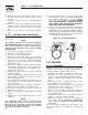
Section 1 — General Information Air-cooled 7 kW, 12 kW and 15 kW Generators 1.4 THE GENERATOR Figure 1.1 – 7 kW, Single Cylinder GH-410 Engine Oil Dipstick Control Panel Data Decal GFCI Outlet Exhaust Enclosure Fuel Regulator Fuel Inlet Oil Filter Battery Compartment Figure 1.
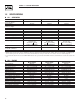
Section 1 — General Information Air-cooled 7 kW, 12 kW and 15 kW Generators 1.5 SPECIFICATIONS 1.5.1 GENERATOR Rated Max. Continuous Power Capacity (Watts*) Rated Voltage Rated Max.
Section 1 — General Information Air-cooled 7 kW, 12 kW and 15 kW Generators 1.6 SYSTEM SET LED The “System Set” LED is lit when all of the following conditions are true: 1. The AUTO/OFF/MANUAL switch is set to the AUTO position. 2. The utility voltage being supplied to the unit is being sensed by the PCB. If the utility sense voltage is not connected to the unit or if it is below 168 volts AC, then the system set light will flash rapidly.
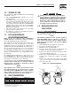
Section 1 — General Information Air-cooled 7 kW, 12 kW and 15 kW Generators 8. Refit the brass hose barb fitting to outlet port #1 and the square headed steel pipe plug to outlet port #2. 9. Reverse procedure steps 1-5 to reinstall demand regulator. 10. Take the plastic plug supplied in the poly-bag with the generator and press it into the 3/4” hole on the bottom of the air cleaner base (Figure 4.6). 11. Reverse the procedure to convert back to natural gas. 1.9.2 12KW AND 15KW, V-TWIN ENGINES 13.
Section 1 — General Information Air-cooled 7 kW, 12 kW and 15 kW Generators 1.10.2 TRANSFER SWITCH 1.10.2.1 7 kW, 12 kW and 15 kW Units The transfer switch shipped with this generator is enclosed in a NEMA 1 enclosure. This type of enclosure is intended for indoor use only. Follow these rules: • Install the transfer switch indoors on a firm, sturdy supporting structure. • To prevent switch distortion, level the switch if necessary.
Section 2 — Post Installation Start-up and Adjustments Air-cooled 7 kW, 12 kW and 15 kW Generators • Spilled electrolyte is to be washed down with an acid neutralizing agent. A common practice is to use a solution of 1 pound (500 grams) bicarbonate of soda to 1 gallon (4 liters) of water. The bicarbonate of soda solution is to be added until the evidence of reaction (foaming) has ceased. The resulting liquid is to be flushed with water and the area dried.
Section 2 — Post Installation Start-up and Adjustments Air-cooled 7 kW, 12 kW and 15 kW Generators 7. When certain that utility supply voltage is compatible with transfer switch and load circuit ratings, turn OFF the utility power supply to the transfer switch. 8. On the generator panel, set the AUTO/OFF/ MANUAL switch to MANUAL. The engine should crank and start. 9. Let the engine warm up for about five minutes to allow internal temperatures to stabilize.
Section 2 — Post Installation Start-up and Adjustments Air-cooled 7 kW, 12 kW and 15 kW Generators 5. Turn ON the utility power supply to the transfer switch, using the means provided (such as a utility main line circuit breaker). 6. Set the AUTO/OFF/MANUAL switch to AUTO. The system is now ready for automatic operation. 7. Turn OFF the utility power supply to the transfer switch. With the AUTO/OFF/MANUAL switch at AUTO, the engine should crank and start when the utility source power is turned OFF.
Section 2 — Post Installation Start-up and Adjustments Air-cooled 7 kW, 12 kW and 15 kW Generators If this procedure or the equipment are not available, locate the nearest Dealer and they can perform the adjustments. NOTE: A service fee may be charged for this adjustment. 2.7 ENGINE GOVERNOR ADJUSTMENT If both AC frequency and voltage are correspondingly high or low, adjust the engine governor as follows: 2.7.1 7 KW UNITS 1. Loosen the governor clamp bolt (Figures 2.3). 2.
Section 3 — Operation Air-cooled 7 kW, 12 kW and 15 kW Generators 7. Restart the unit. 8. Slowly turn the idle adjust screw to adjust the no-load idle frequency to 63-63.5 Hz (with door open). 9. The governor is now set. 3.1 2.7.3 1. Set the generator’s AUTO/OFF/MANUAL switch to AUTO. 2. Turn OFF the utility power supply to the transfer switch using the means provided (such as a utility main line circuit breaker). 3. The unit will start, and the transfer switch will transfer to standby. 4.
Section 3 — Operation Air-cooled 7 kW, 12 kW and 15 kW Generators 3.2.2 “OFF” POSITION 3.3.1 12 VDC ACCESSORY OUTLET This switch position shuts down the engine. This position also prevents automatic operation. Your generator is equipped with a 12 VDC accessory outlet in the Generator Control Panel. (Figure 3.
Section 3 — Operation Air-cooled 7 kW, 12 kW and 15 kW Generators • If utility source voltage drops below about 60 percent of the nominal supply voltage, the sensor energizes a 15-second timer. • Once the timer has expired, the engine will crank and start. B. Engine Warm-up Time Delay • This mechanism lets the engine warm up for about 10 seconds before the load is transferred to the standby source. C. Standby Voltage Sensor • This sensor monitors generator AC output voltage.
Section 3 — Operation Air-cooled 7 kW, 12 kW and 15 kW Generators 5. Use the manual transfer handle inside the transfer switch to move the main contacts back to their UTILITY position, i.e., loads connected to the utility power source (Figure 3.2). 6. Turn ON the utility power supply to the transfer switch using the means provided. 7. Set the system to automatic operation as outlined in “Automatic Transfer Operation,” Section 3.3. 3.6 3.7.2 This switch’s contacts (Figure 3.
Section 4 — Maintenance Air-cooled 7 kW, 12 kW and 15 kW Generators 3.7.4 OVERSPEED This feature protects the generator from damage by shutting it down if it happens to run faster than the preset limit. This protection also prevents the generator from supplying an output that could potentially damage appliances connected to the generator circuit. Contact the nearest Authorized Dealer if this failure occurs. 4.1 FUSES The generator panel's 15-amp fuse (Figure 4.
Section 4 — Maintenance Air-cooled 7 kW, 12 kW and 15 kW Generators 4.3 CHANGING THE ENGINE OIL 4.3.1 ENGINE OIL RECOMMENDATIONS Use oil of American Petroleum Institute (API) Service Class SG, SH or SJ. Use all season SAE 5W-30 Synthetic oil. Organic break-in oil is required before using synthetic oil. NOTE: The unit is supplied with “break-in” oil. See the “Break-in Procedure,” Section 3.1, for the first required oil change.
Section 4 — Maintenance Air-cooled 7 kW, 12 kW and 15 kW Generators Figure 4.7 — 12 kW and 15 kW Engine Air Cleaner Screw Cover Filter 4.7 BATTERY MAINTENANCE The battery should be inspected per the “Service Schedule,” Section 4.13. The following procedure should be followed for inspection: 1. Inspect the battery posts and cables for tightness and corrosion. Tighten and clean as necessary. 2. Check the battery fluid level of unsealed batteries and, if necessary, fill with Distilled Water Only.
Section 4 — Maintenance Air-cooled 7 kW, 12 kW and 15 kW Generators batteries present a risk of fire because Lead-acid they generate hydrogen gas. The following procedures are to be followed: • DO NOT SMOKE when near the battery; • DO NOT cause flame or spark in battery area; and • Discharge static electricity from body before touching the battery by first touching a grounded metal surface.
Section 4 — Maintenance Air-cooled 7 kW, 12 kW and 15 kW Generators exhaust from this product gets extremely The hot and remains hot after shutdown. High grass, weeds, brush, leaves, etc. must remain clear of the exhaust. Such materials may ignite and burn from the heat of the exhaust system. maximum ambient temperature for the gen The erator is 40° C (104° F). 4.10 ATTENTION AFTER SUBMERSION If the generator has been submerged in water, it must not be started and operated.
Section 4 — Maintenance Air-cooled 7 kW, 12 kW and 15 kW Generators 4.13 SERVICE SCHEDULE ATTENTION: It is recommended that all service work be performed by the nearest Authorized Dealer. SYSTEM/COMPONENT X = Action R = Replace as Necessary * = Notify Dealer if Repair is Needed.
Section 5 — Troubleshooting Air-cooled 7 kW, 12 kW and 15 kW Generators 5.1 TROUBLESHOOTING GUIDE Problem Cause The engine will not crank. 1. Fuse blown. 2. 3. 4. 5. The engine cranks but will not start. Correction 1. Replace 15A fuse in generator control panel. Loose, corroded or defective 2. Tighten, clean or replace battery cables. as necessary. Defective starter contactor. (7 kW) 3. * Defective starter motor. 4. * Dead Battery. 5. Charge or replace battery. 1. Out of fuel. 2.
Section 6 — Notes Air-cooled 7 kW, 12 kW and 15 kW Generators 25
Section 6 — Notes Air-cooled 7 kW, 12 kW and 15 kW Generators 26
Section 6 — Notes Air-cooled 7 kW, 12 kW and 15 kW Generators 27
Section 7 — Electrical Data Air-cooled 7 kW, 12 kW and 15 kW Generators Wiring Diagram – V-Twin – Drawing No. 0E9016 ENGINE WIRING 3 2 1 DIAGRAM KEY BA - BRUSH ASSEMBLY BCR - BATTERY CHARGE RELAY CB1 - MAIN OUTPUT BREAKER CB2 - CIRCUIT BREAKER, ALTERNATOR EXCITATION CB3 - CIRCUIT BREAKER, EXTERNAL OUTLET, PUSH/PULL D - DIODE DSW - PCB MOUNTED DIP SWITCH FS - FUEL SOLENOID F1 - FUSE 15 AMP F2 - FUSE 7.
Section 7 — Electrical Data Air-cooled 7 kW, 12 kW and 15 kW Generators Wiring Diagram – V-Twin – Drawing No.
Section 7 — Electrical Data Air-cooled 7 kW, 12 kW and 15 kW Generators Electrical Schematic – V-Twin – Drawing No.
Section 7 — Electrical Data Air-cooled 7 kW, 12 kW and 15 kW Generators Electrical Schematic – V-Twin – Drawing No.
Section 7 — Electrical Data Air-cooled 7 kW, 12 kW and 15 kW Generators Wiring Diagram – Single Cylinder – Drawing No. 0E9014 3 2 ENGINE WIRING DIAGRAM KEY BA - BRUSH ASSEMBLY BCR - BATTERY CHARGE RELAY CB1 - MAIN OUTPUT BREAKER CB2 - CIRCUIT BREAKER, ALTERNATOR EXCITATION CB3 - CIRCUIT BREAKER, EXTERNAL OUTLET, PUSH/PULL D - DIODE DSW - PCB MOUNTED DIP SWITCH FS - FUEL SOLENOID F1 - FUSE 15 AMP F2 - FUSE 7.
Section 7 — Electrical Data Air-cooled 7 kW, 12 kW and 15 kW Generators Wiring Diagram – Single Cylinder – Drawing No.
Section 7 — Electrical Data Air-cooled 7 kW, 12 kW and 15 kW Generators Electrical Schematic – Single Cylinder – Drawing No.
Section 7 — Electrical Data Air-cooled 7 kW, 12 kW and 15 kW Generators Electrical Schematic – Single Cylinder – Drawing No.
Section 7 — Electrical Data Air-cooled 7 kW, 12 kW and 15 kW Generators Wiring Diagram – 8 Circuit Load Center – Drawing No.
Section 7 — Electrical Data Air-cooled 7 kW, 12 kW and 15 kW Generators Wiring Diagram – 8 Circuit Load Center – Drawing No.
Section 7 — Electrical Data Air-cooled 7 kW, 12 kW and 15 kW Generators Wiring Diagram – 12 Circuit Load Center – Drawing No.
Section 7 — Electrical Data Air-cooled 7 kW, 12 kW and 15 kW Generators Wiring Diagram – 12 Circuit Load Center – Drawing No.
Section 7 — Electrical Data Air-cooled 7 kW, 12 kW and 15 kW Generators Electrical Schematic – 8 Circuit Load Center – Drawing No.
Section 7 — Electrical Data Air-cooled 7 kW, 12 kW and 15 kW Generators Electrical Schematic – 12 Circuit Load Center – Drawing No.
Section 8 — Exploded Views and Parts Lists Air-cooled 7 kW, 12 kW and 15 kW Generators Enclosure – Drawing No.
Section 8 — Exploded Views and Parts Lists Air-cooled 7 kW, 12 kW and 15 kW Generators Enclosure – Drawing No. 0F0080-C ITEM PART NO. QTY.
Section 8 — Exploded Views and Parts Lists Air-cooled 7 kW, 12 kW and 15 kW Generators Control Panel – Drawing No.
Section 8 — Exploded Views and Parts Lists Air-cooled 7 kW, 12 kW and 15 kW Generators Control Panel – Drawing No. 0E9162-J ITEM PART NO. QTY.
Section 8 — Exploded Views and Parts Lists Air-cooled 7 kW, 12 kW and 15 kW Generators 7 kW, 8 Circuit Load Center Assembly – Drawing No.
Section 8 — Exploded Views and Parts Lists Air-cooled 7 kW, 12 kW and 15 kW Generators 7 kW, 8 Circuit Load Center Assembly – Drawing No. 0E7975-B ITEM 1 2 3 3A 3B 3C 3D 4 5 6 7 8 9 10 11 12 13 14 15 16 17 18 19 20 21 22 23 24 25 26 27 28 29 30 31 32 33 34 35 36 37 PART NO. QTY.
Section 8 — Exploded Views and Parts Lists Air-cooled 7 kW, 12 kW and 15 kW Generators 12 kW and 15 kW, 12 Circuit Load Center Assembly – Drawing No.
Section 8 — Exploded Views and Parts Lists Air-cooled 7 kW, 12 kW and 15 kW Generators 12 kW and 15 kW, 12 Circuit Load Center Assembly – Drawing No. 0E7973-F ITEM 1 2 3 3A 3B 3C 3D 4 5 6 7 8 9 10 11 12 13 14 15 16 17 18 19 20 21 22 23 24 25 26 27 28 29 30 31 32 33 34 35 36 37 38 39 40 PART NO. QTY.
50 42 41 40 38 45 44 39 143 37 46 43 29 28 50 52 55 51 26 31 32 3 47 48 49 27 3 140 34 53 30 25 54 56 144 24 23 33 35 36 34 58 57 59 16A 16A 60 18 17 16B 21 22 61 63 64 20 14 13 65 8 12 11 1 10 2, 5, 19, 20, 39, 40, 47, 64, 93, 140 8, 11, 12, 13 4, 5, 6 16A, 16B, 17, 18 7, 47, 48, 49, 50, 51, 52, 53, 54, 56, 57, 58, 59, 60, 63, 64 47, 48, 49, 50, 51, 52, 53, 54, 56, 57, 58, 59, 60, 62, 63, 64 27, 28, 29 3, 32, 33, 34, 35, 36, 40, 72 19 62 15 66 67 68
Section 8 — Exploded Views and Parts Lists Air-cooled 7 kW, 12 kW and 15 kW Generators GT-990/760 Engine – Drawing No. 0E8774-M Part 1 ITEM PART NO. QTY.
Section 8 — Exploded Views and Parts Lists Air-cooled 7 kW, 12 kW and 15 kW Generators GT-990/760 Engine – Drawing No.
Section 8 — Exploded Views and Parts Lists Air-cooled 7 kW, 12 kW and 15 kW Generators GT-990/760 Engine – Drawing No. 0E8774-M Part 2 ITEM PART NO. QTY.
Section 8 — Exploded Views and Parts Lists Air-cooled 7 kW, 12 kW and 15 kW Generators 7 kW Generator – Drawing No.
Section 8 — Exploded Views and Parts Lists Air-cooled 7 kW, 12 kW and 15 kW Generators 7 kW Generator – Drawing No. 0D3504-E ITEM PART NO. QTY.
Section 8 — Exploded Views and Parts Lists 28 29 27 28 17 13 11 23 5 24 43 7 21 34 12 33 39 6 8 4 9 31 37 32 31 28 40 38 3 20 14 2 22 15 1 19 10 17 32 10 19 32 30 25 24 16 26 29 36 35 28 18 36 41 42 10 41 31 36 32 35 36 Air-cooled 7 kW, 12 kW and 15 kW Generators 12 kW and 15 kW Generator – Drawing No.
Section 8 — Exploded Views and Parts Lists Air-cooled 7 kW, 12 kW and 15 kW Generators 12 kW and 15 kW Generator – Drawing No. 0D3417-L ITEM 1 2 3 4 5 6 7 8 9 10 11 12 13 14 15 16 17 18 19 20 21 22 23 24 25 26 27 28 29 30 31 32 33 34 35 36 37 38 39 40 41 42 43 PART NO. QTY.
Section 8 — Exploded Views and Parts Lists 42 17 31 25 30 29 28 27 37 24 35 36 23 33 45 43 39 19 18 20 34 46 44 11 32 22 48 47 26 41 38 40 51 25 12 13 14 50 49 1 6 54 16 52 1 2 5 10 4 3 7 11 8 9 Air-cooled 7 kW, 12 kW and 15 kW Generators GN410 Engine – Drawing No.
Section 8 — Exploded Views and Parts Lists Air-cooled 7 kW, 12 kW and 15 kW Generators GN410 Engine – Drawing No. 0F3981-A Part 1 ITEM 1 2 3 4 5 6 7 8 9 10 11 12 13 14 15 16 17 18 19 20 21 22 23 24 25 26 27 28 29 30 31 32 33 34 35 36 37 38 39 40 41 42 43 44 45 46 47 48 49 50 51 52 53 54 PART NO.
Section 8 — Exploded Views and Parts Lists 26 34 27 60 6 12 7 19 6 20 41 43 45 21 40 3 39 5 6 28 14 1 17 18 13 8 4 31 24 30 6 9 11 52 42 48 10 32 25 18 18 34 33 2 6 37 6 Air-cooled 7 kW, 12 kW and 15 kW Generators GN410 Engine – Drawing No.
Section 8 — Exploded Views and Parts Lists Air-cooled 7 kW, 12 kW and 15 kW Generators GN410 Engine – Drawing No. 0F3981-A Part 2 ITEM 1 2 3 4 5 6 7 8 9 10 11 12 13 14 15 16 17 18 19 20 21 22 23 24 25 26 27 28 29 30 31 32 33 34 35 36 37 38 39 40 41 42 43 44 45 46 47 48 49 50 51 52 PART NO.
Section 8 — Exploded Views and Parts Lists Air-cooled 7 kW, 12 kW and 15 kW Generators Gas Regulator – Drawing No. 0D8720-H 10 8 30 9 2 12 11 21 5 10 28 4 20 3 25 24 23 10 1 22 37 7KW 19 16 26 32 14 11 28 17 19 13 27 31 12 29 18 15 12 23 22 24 26 15 29 14 11 18 20 16 17 28 25 13 21 ITEM 1 2 3 4 5 8 9 10 11 12 13 14 15 16 17 18 19 20 21 62 PART NO. QTY.
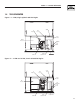
CBHOM-F CBHOM-F CBHOM-F CBHOM-F CBHOM-F TYPE HOM 120/240v TYPE HOM 120/240v TYPE HOM 120/240v TYPE HOM 120/240v TYPE HOM 120/240v CBHOM-F M6PEM-T M6PEM-T LEFT SIDE VIEW 622 [24.5"] 604 [23.5"] TRANSFER SWITCH (IF SUPPLIED) M6PEM-T CBHOM-F TYPE HOM 120/240v 716 [28"] 743 [29.25"] TYPE HOM 120/240v TYPE HOM 120/240v TYPE HOM 120/240v CBHOM-F CBHOM-F CBHOM-F CBHOM-F CBHOM-F TYPE HOM 120/240v TYPE HOM 120/240v TYPE HOM 120/240v M6PEM-T 308 [12"] 207 [8.14"] 76.2mm [3.
Section 10 – Warranty Air-cooled 7 kW, 12 kW and 15 kW Generators NOTE: This Emission Control Warranty Statement pertains to this product only IF the generator size is 15 kW or below. CALIFORNIA EMISSION CONTROL WARRANTY STATEMENT YOUR WARRANTY RIGHTS AND OBLIGATIONS The California Air Resources Board (CARB) and Generac Power Systems, Inc. (Generac) are pleased to explain the Emission Control System Warranty on your new engine.
Section 10 – Warranty Air-cooled 7 kW, 12 kW and 15 kW Generators EMISSION CONTROL SYSTEM WARRANTY Emission Control System Warranty (ECS Warranty) for 1995 and later model year engines: (a) Applicability: This warranty shall apply to 1995 and later model year engines. The ECS Warranty Period shall begin on the date the new engine or equipment is purchased by/delivered to its original, end-use purchaser/owner and shall continue for 24 consecutive months thereafter.
Section 10 – Warranty Air-cooled 7 kW, 12 kW and 15 kW Generators GENERAC POWER SYSTEMS "TWO YEAR" LIMITED WARRANTY FOR GUARDIAN® "PREPACKAGED EMERGENCY AUTOMATIC STANDBY GENERATORS" For a period of two years from the date of original sale, Generac Power Systems, Inc. (Generac) warrants that its Guardian generator will be free from defects in material and workmanship for the items and period set forth below.