.6L 20/25/30 kW Models Serial Number STANDBY GENERATOR OWNER'S MANUAL A new standard of reliability Not intended for use in critical life support applications. —CAUTION— ONLY QUALIFIED ELECTRICIANS OR CONTRACTORS SHOULD ATTEMPT INSTALLATION! DEADLY EXHAUST FUMES. OUTDOOR INSTALLATION ONLY! This manual should remain with the unit. Cover113 Rev. B 09/07 Catalog Number OMASPEA025-2 Part No.
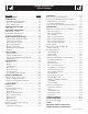
Standby Generator Sets Table of Contents SECTION PAGE SAFETY RULES ................................................ 1-1 OPERATION ...........................................................9-1 INTRODUCTION .....................................................1-3 Read this Manual Thoroughly ...................................1-3 Operation and Maintenance ......................................1-3 How to Obtain Service ..............................................1-3 IDENTIFICATION RECORD .................
Standby Generator Sets Important Safety Instructions WARNING: GENERAL HAZARDS The engine exhaust from this product contains chemicals known to the state of California to cause cancer, birth defects or other reproductive harm.
Standby Generator Sets Important Safety Instructions • Generators installed with an automatic transfer switch will crank and start automatically when normal (utility) source voltage is removed or is below an acceptable preset level. To prevent such automatic start-up and possible injury to personnel, disable the generator’s automatic start circuit (battery cables, etc.) before working on or around the unit. Then, place a “Do Not Operate” tag on the generator control panel and on the transfer switch.
Standby Generator Sets Important Safety Instructions INTRODUCTION symbol points out potential explosion This hazard. Thank you for purchasing this model of the standby generator set product line. This symbol points out potential fire hazard. symbol points out potential electrical shock This hazard. Every effort was expended to make sure that the information and instructions in this manual were both accurate and current at the time the manual was written.
Standby Generator Sets General Information IDENTIFICATION RECORD NOTE: For actual information related to this particular model, please refer to the Manual Drawing Listing located at the end of this manual, or to the data label affixed to the unit. DATA LABEL Every generator set has a DATA LABEL that contains important information pertinent to the generator.
Standby Generator Sets Equipment Description EQUIPMENT DESCRIPTION COOLANT RECOMMENDATIONS This equipment is a revolving field, alternating current generator set. It is powered by a gaseous fueled engine operating at 1800 rpm for 4-pole direct drive units, 3600 rpm for 2-pole direct drive units and 2300 - 3000 rpm for quiet drive gear units. See the Specifications section for exact numbers.
Standby Generator Sets Engine Protective Devices ENGINE PROTECTIVE DEVICES OVERCRANK SHUTDOWN The standby generator may be required to operate for long periods of time without an operator on hand to monitor such engine conditions as coolant temperature, oil pressure or rpm.
Standby Generator Sets Fuel Systems FUEL SYSTEM PROPANE VAPOR WITHDRAWAL FUEL SYSTEM FUEL REQUIREMENTS This type of system utilizes the vapors formed above the liquid fuel in the supply tank. Approximately 10 to 20 percent of the tank capacity is needed for fuel expansion from the liquid to the vapor state. The vapor withdrawal system is generally best suited for smaller engines that require less fuel.
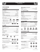
Standby Generator Sets Specifications SPECIFICATIONS Engine Lubrication System Type of Oil Pump ...................................................................... Gear Oil Filter .............................................................Full Flow, Cartridge Crankcase Oil Capacity ....................................................4 U.S. qts. GENERATOR Type ............................................................................. Synchronous Rotor Insulation .................................
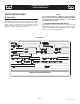
Standby Generator Sets Specifications Figure 6.
Standby Generator Sets General Information GENERATOR AC LEAD CONNECTIONS ALTERNATOR POWER WINDING CONNECTIONS See “Voltage Codes”. This generator may be rated at any one of three voltages, either single-phase or three-phase. The electrical wires in the unit’s AC connection (lower) panel should be installed according to the number of leads and the voltage/phase required for the application. If there are any questions regarding lead connection, refer to the wiring diagrams at the back of this manual.
Standby Generator Sets Installation PRIOR TO INITIAL START-UP INSTALLATION Refer to the separate “Installation Guide” supplied with the unit. to initially starting the generator, it must Prior be properly prepared for use. Any attempt to PREPARATION BEFORE START-UP The instructions in this section assume that the standby generator has been properly installed, serviced, tested, adjusted and otherwise prepared for use by a competent, qualified installation contractor.
Standby Generator Sets Installation • Open the valve to the engine fuel line. • Bleed the fuel system of air. (necessary for long fuel lines). • Open the generator main line circuit breaker. • Connect a manometer to the gas line and record the static pressure. It must be as listed in the Specifications. • Insert the fuse into the control panel. • Move the AUTO/OFF/MANUAL switch to the manual position. The engine should now crank and start. • Check voltage at the generator terminals.
Standby Generator Sets Operation GENERATOR CONTROL AND OPERATION not crank the engine continuously for longer Do than 30 seconds, or the heat may Refer to the appropriate control panel operator’s manual for this unit. • • OPERATING UNIT WITH MANUAL TRANSFER SWITCH If the generator was installed in conjunction with a transfer switch capable of manual operation only, the following procedure applies.
Standby Generator Sets Maintenance MAINTENANCE PERFORMED BY SERVICE FACILITIES COOLING SYSTEM Air intake and outlet openings in the generator compartment must be open and unobstructed for continued proper operation. This includes such obstructions as high grass, weeds, brush, leaves and snow. working on the generator, ensure the fol Before lowing: Without sufficient cooling and ventilating air flow, the engine/generator quickly overheats, which causes it to shut down. (See the installation diagram.
Standby Generator Sets Maintenance EXERCISE SYSTEM Figure 10.1 - Oil Dipstick and Oil Fill Cap Start the generator engine at least once every seven days and let it run at least 20 minutes. For more detailed exercise information, see the respective sections in the Control Panel Technical Manual that is supplied with the unit. OIL FILL CAP INSPECT COOLING SYSTEM • Inspect engine cooling system. See “Maintenance Schedule”. • Check hoses for damage, deterioration, leaks, etc.
Standby Generator Sets Maintenance CHANGING ENGINE OIL Figure 10.3 – Engine Air Cleaner Refer to maintenance performed by service facilities for engine oil and filter change frequencies. Air Cleaner Drain the oil while the engine is still warm from running. This means warm up the engine, shut it down and drain immediately as follows: 1. Remove OIL DRAIN HOSE from its retaining clip. 2. Loosen and remove OIL DRAIN HOSE CAP. Drain oil completely into suitable container. 3.
Standby Generator Sets Maintenance MISCELLANEOUS MAINTENANCE 3. Have the state of charge and condition checked. This should be done with an automotive-type battery hydrometer. CLEANING THE GENERATOR DANGER Keep the generator as clean and as dry as possible. Dirt and moisture that accumulates on internal generator windings have an adverse effect on insulation resistance. Periodically clean generator exterior surfaces. A soft brush may be used to loosen caked on dirt.
Standby Generator Sets Service Schedule SERVICE SCHEDULE The following is a recommended maintenance schedule for small standby and residential generator sets. The established intervals in the schedule are the maximum recommended when the unit is used in an average service application. They will need to be decreased (performed more frequently) if the unit is used in a severe application.
Standby Generator Sets Service Schedule Maintenance Tasks Level 1 Recommended to be done monthly 10 Hrs. Level 2 Task Comp. (DateInitials) Required to be done 3 months/ Break-in 30 Hrs. 1. Disable the unit from operating per the first page warning. 2. Check the engine oil level. Adjust as necessary. 3. Check the engine coolant level. Adjust as necessary. 4. Check the engine coolant thermal protection level. Correct as necessary. 5. Check the natural gas delivery system on gas engine driven units.
Standby Generator Sets Service Schedule Maintenance Tasks Level 1 RecomTask mended Comp. to be done (Datemonthly In itials) 10 Hrs. Level 2 Required to be done 3 months/ Break-in 30 Hrs. Level 3 Task Comp. (DateInitials) Required to be done Semiannually 50 Hrs. Level 4 Task Comp. (DateInitials) Required to be done Annually 100 Hrs. Task Comp. (DateInitials) 13.
Standby Generator Sets Troubleshooting TROUBLESHOOTING GUIDE PROBLEM CAUSE CORRECTION Engine won’t crank. 1. 15 amp fuse blown. 2. Loose or corroded or defective battery cables. 3. Defective starter contactor. 4. Defective starter motor. 5. Dead or Defective Battery. 6. 5 amp fuse blown. 1. Replace fuse. 2. Tighten, clean or replace battery cables as necessary. 3. Replace contactor.* 4. Replace starter motor.* 5. Remove, change or replace battery. 6. Replace fuse.* Engine cranks but won't start 1.
Standby Generator Sets Notes
Standby Generator Sets Notes
Standby Generator Sets Notes
Standby Generator Sets Notes
1 2 3 4 5 6 7 8 9 10 11 12 13 14 15 16 17 18 19 20 21 22 (1) 23 24 25 26 27 28 0G4827 0G2927 0G2827 0G3451C 0G0820A 0G4452 020746 049226 051713 022129 0G4825 0G4826 0G2926 0G3682 0G5584 0G3685 0G2826 0G3683 0G6573 0G3686 0G3452C 0G3684 0G3687 0G5909 0G6103 0A5382A 075591 051787 0A5601A 075554B 075554E 0A9375 022152 0G4196 042558 049814 0G0965B 053607 051769 023365 0F3353 072578 0G3787 0A8830 077043E 0G2070 1 1 1 1 1 1 4 4 4 4 1 1 1 1 1 1 1 1 1 1 1 1 1 1 1 1 2 4 1 4 4 4 4 1 1 4 1 1 1 4 6 1 10 4 1 1 ASSY
1 A B C D E F G H J K L 2 A B C D E F G H J K L N/A 0D5543 0D5544 0A2077 0G4499 0C2265 0C2264 0E7890 0G4497 052619 023897 049226 051716 0E3257 N/A 1 1 1 1 2 2 1 1 2 4 2 2 7 UL BREAKER BQ2 CB 0090A 2P 240V S BQ2 LL CB 0100A 2P 240V S BQ2 LL CB 0125A 2P 240V S BQ2 LL CB COVER 20-25K 1P (BQ2) SCREW PHTT M4-0.7 X 12 ZYC WASHER LOCK #8-M4 BRKT CB MTG BACK CIRCUIT BREAKER SUPPORT (BQ) SCREW HHC M5-0.8 X 20 G8.8 WASHER FLAT #10 ZINC WASHER LOCK M5 NUT HEX M5-0.8 G8 CLEAR ZINC SCREW HWHTF M6-1.
1 2 3 4 5 6 7 8 9 10 11 12 13 14 15 18 19 20 21 22 23 24 25 26 27 28 29 30 31 32 33 34 35 36 37 43 44 45 46 47 48 0F1823A 0F3078 0F2606 036261 0E7358 052777 0G3958D 0F1262 0F1263 0F1264 0F1725C 067680 0E6875A 055911 0F5459 0F5462 0A5062J 029673 049350 0F1958 082573 0E4494 0F3215 0F6305 0F6305A 0F5886 051713 049226 0F5752F 0F5884 0F5896 0C2265 0C3990 091526 051716 043182 051714 0F3192 0E7403C 0G4583 0F2627 COMPONENTS INCLUDED IN 0G4577E 1 ENCL HSB CONTROL PANEL 1 COVER CONTROL PANEL 1 HINGE CONTINUOUS H-PA
1 2 3 4 5 6 7 8 9 10 11 12 13 14 15 16 17 18 19 20 21 23 24 25 26 27 28 29 30 31 32 33 34 35 (1) 36 37 38 39 0G3418 0G3421 0G3419 0E9837B 0G3553 0E3257 0G4080 099502 0G4070 0G4072 0G4071 046627 052250 022473 022097 0C8566 045771 0C2454A 042568 0G3573 0G3574 0G3420 080713 076749 048031C 029032 0G4451 055934N 0F9504 0G0568 0G3433 0E2507 0A2628 029333A 042907 027482 022129 039253 1 1 1 1 1 2 1 6 1 1 1 1 2 8 8 4 4 28 4 1 1 1 1 1 2 1 REF 2 1 1 1 1 1 1 4 4 4 4 RADIATOR SUPPORT LH SIDE 1.6L VENTURI 1.
1 2 3 4 5 6 7 8 9 10 11 13 14 15 16 17 18 0G3343 027482 070936 070936C 039253 022145 022129 045771 071956 051730 021991 026850 049813 055414 047411 022097 022473 1 2 2 2 8 12 12 4 4 4 1 1 1 1 1 1 5 MOUNTING BASE 1.6L 2007 C1 WASHER SHAKEPROOF EXT 5/16 STL DAMPENER VIBRATION VIB. ISO. 70-75 DURO SCREW HHC M8-1.25 X 20 G8.8 WASHER FLAT 5/16 ZINC WASHER LOCK M8-5/16 NUT HEX M8-1.25 G8 YEL CHR WASHER FLAT M8 SCREW HHC M8-1.25 X 60 G8.8 EARTH STRAP WASHER SHAKEPROOF EXT 1/4 STL NUT HEX M6 X 1.
1 2 3 4 5 6 7 8 9 10 11 12 13 14 15 16 0F3408C 0F3411 025507 059980 046526 077483 050331A 050331 038805J 038804M 045771 022131 027482 0F3976 0C2454 022145 1 1 1 1 1 REF REF REF 1 1 REF 1 1 1 4 REF BATTERY TRAY, C1 & C2 STRAP BATTERY RETAINMENT WASHER SHAKEPROOF EXT 7/16 STL SCREW HHC M10-1.5 X 25 G10.9 WASHER LOCK M10 BATTERY 12VDC 75-AH 26 BATTERY POST COVER RED + BATTERY POST COVER BLK CABLE BATTERY BLACK #1 X 30.00 CABLE BATTERY RED #1 X 21.00 NUT HEX M8-1.
1 2 3 4 5 6 7 8 9 10 11 12 13 14 15 16 17 18 19 20 21 22 23 24 25 26 27 28 29 30 31 32 33 34 35 36 37 38 39 40 41 42 43 44 45 46 47 48 49 50 51 52 53 54 55 56 57 58 59 60 61 62 0G0207 0G0834 0G0820 0E9747 0G0839 0G0781 0G0722 0G4059 0G4604 0G3424 0G4863 0G0786 0G4605 0F9617A 0A1354B 0G0823 0G4949 0G3900 0D2244M 036710 0C5479 059980 046526 022131 0G3922 0G0464 0G0465 052858 051735 0G3920 0A7387 039414 022129 022145 029333A 057821 045771 022507 022097 022473 090388 0A5768 0A6751 035579 0A8584 0C1852 070928 0
1 2 3 4 5 6 7 8 9 10 11 12 13 14 15 16 098290 098941A 098958A 098942A 098225 043146 022097 084543A 098783 037398 0E1326 0G4451 064526 029333A 022507 0E1694 1 1 REF 1 2 3 5 1 1 2 1 1 1 10 2 1 ASM MOTOR STEPPER HOUSING GOVERNOR CONNECTOR CONNECTOR INTERFACE ASSEMBLY COVER CONNECTOR HOUSING SCREW FHM #2 X 5/8 SELF TAP SCREW HHC M6-1.0 X 10 G8.8 WASHER LOCK M6-1/4 SCREW PHM M3-0.5 X 12MM LEVER STEPPER MOTOR NUT LOCK HEX #10-32 NYL INS ASSY.
1 2 3 4 5 6 7 (1) 8 9 10 11 12 13 14 15 026812 075580 0G1397A 0G1397B 039253 022145 022129 045771 0F1570 0A6344 0C5210 025424 0C5210 0A5547 0G3178 0D1509 2 1 1 1 2 2 4 2 1 1 1 1 1 1 1 1 ELBOW 90D 3/4 NPT FLANGE FUEL INLET FUEL REG. REWORK 1.6L 3600 '07 (3600RPM) FUEL REG. REWORK 1.6L 1800 '07 (1800RPM) SCREW HHC M8-1.25 X 20 G8.8 WASHER FLAT 5/16 ZINC WASHER LOCK M8-5/16 NUT HEX M8-1.
(1) 1 (1) 2 (2) 3 (1) 4 (1) 5 6 7 8 9 10 11 12 13 14 15 16 17 18 19 20 21 22 0G3337 0G3336 077992 0G3341 0G3335 0F4487A 022127 022097 022473 0C2454 0F5048D 0F5049 0F8869D 089961 078115 0G4029 0G4029A 0F3890 0E3257 0912970090 0G4029B 0F3890B 1 1 16 2 1 1 1 1 1 16 2 2 1 1 18 2 1 5 4 2 1 4 ROOF 1.6L C1 REAR INTAKE WRAP 1.6L C1 NUT HEX LOCK M6-1.0 SS NY INS RIGHT SIDE DOOR 1.6L C1 FRONT DISCHARGE WRAP 1.
1 2 3 4 5 6 7 8 9 10 11 12 13 14 15 16 17 0F7366 0F7647 0F8095 0G3576 0E3257 0F7644 0C6119 036434 036449 022129 022259 038750 0G3575 0F3794A 022097 049813 022473 1 1 1 1 4 2 1 3 3 6 6 1 1 1 1 1 6 MUFFLER C1 MUFFLER SADDLE PIPE EXHAUST OUTLET EXHAUST PIPE LOWER 1.6L SCREW HWHTF M6-1.0 X 16 MUFFLER STRAP BOLT U 5/16-18 X 2-1/4 BOLT U 5/16-18 X 2.09 SADDLE 2 INCH WASHER LOCK M8-5/16 NUT HEX 5/16-18 STEEL SCREW HHC M6-1.0 X 30 G8.8 EXHAUST PIPE UPPER 1.
BackPg001 Rev.