® POWER SYSTEMS, INC. Installation and Owner’s Manual Air-cooled Automatic Standby Generators Model: 05176-0 (13 kW NG, 15 kW LP) GENERAC POWER SYSTEMS, INC. R R *This manual should remain with the unit.* Not intended for use as Primary Power in place of utility or in life-support applications. DANGER DEADLY EXHAUST FUMES.
INTRODUCTION Thank you for purchasing this model by Generac Power Systems Inc.. This model is a compact, high performance, air-cooled, engine-driven generator designed to automatically supply electrical power to operate critical loads during a utility power failure. This unit is factory installed in an all-weather, metal enclosure that is intended exclusively for outdoor installation. This generator will operate using either vapor withdrawn liquid propane (LP) or natural gas (NG).
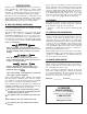
Table of Contents Air-cooled 15 kW Generators Introduction ........................Inside Front Cover 4.2 Automatic Transfer Operation ..................... 14 Read This Manual Thoroughly ........................ IFC 4.3 Sequence of Automatic Operation ............... 14 Contents .......................................................... IFC 4.4 Manual Operation ....................................... 15 Operation and Maintenance ............................ IFC 4.4.
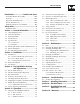
IMPORTANT SAFETY INSTRUCTIONS Air-cooled 15 kW Generators SAVE THESE INSTRUCTIONS – The manufacturer suggests that these rules for safe operation be copied and posted near the unit’s installation site. Safety should be stressed to all operators and potential operators of this equipment. WARNING: The engine exhaust from this product contains chemicals known to the state of California to cause cancer, birth defects or other reproductive harm.
IMPORTANT SAFETY INSTRUCTIONS Air-cooled 15 kW Generators ELECTRICAL HAZARDS • All generators covered by this manual produce dangerous electrical voltages and can cause fatal electrical shock. Utility power delivers extremely high and dangerous voltages to the transfer switch as does the standby generator when it is in operation. Avoid contact with bare wires, terminals, connections, etc., while the unit is running.
Section 1 — General Information Air-cooled 15 kW Generators DANGER qualified electricians or contractors should Only attempt such installations, which must comply strictly with applicable codes, standards and regulations. 1.1 UNPACKING/INSPECTION After unpacking, carefully inspect the contents for damage. • This standby generator set has been factory supplied with a weather protective enclosure that is intended for outdoor installation only.
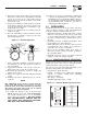
Section 1 — General Information Air-cooled 15 kW Generators 1.4 THE GENERATOR Figure 1.1 – 15 kW, V-twin GT-990 Engine Oil Dipstick Data Decal Control Panel Exhaust Enclosure Fuel Regulator Fuel Inlet Oil Filter Battery Compartment Composite Base Figure 1.
Section 1 — General Information Air-cooled 15 kW Generators 1.5 SPECIFICATIONS 1.5.1 GENERATOR Rated Max. Continuous Power Capacity (Watts*).......................... 13,000 NG/15,000 LP Rated Voltage........................................................120/240 Rated Max. Continuous Load Current (Amps) 120 Volts + ...................................... 108.3 NG/125.0 LP 240 Volts .............................................. 54.2 NG/62.5 LP Main Line Circuit Breaker..................................
Section 2 — Installation Air-cooled 15 kW Generators 4. Remove the engine air in baffle located on the lefthand side of the battery compartment. Two M6 screws are located on top of the baffle and two M6 screws are located on the inside of the baffle towards the back. 5. Remove the small hose clamp and hose from the fuel regulator. It may be necessary to pry the hose off of the brass fitting using a screwdriver to gently lift up the hose edge. 6.
Section 2 — Installation Air-cooled 15 kW Generators Remote monitoring functions are only available with the AUTO/OFF/MANUAL switch in the Auto or Manual position. Since the contacts are SPDT, it is possible to monitor either state of each alarm function. Relay 1: Engine running, normally closed.
Section 2 — Installation Air-cooled 15 kW Generators Connect power source load conductors to clearly marked transfer mechanism terminal lugs as follows 1. Connect UTILITY (NORMAL) power source cables to switch terminals N1, N2. 2. Connect customer LOAD leads to switch terminals T1, T2. Conductors must be properly supported, of approved insulative qualities, protected by approved conduit, and of the correct wire gauge size in accordance with applicable codes.
Section 3 — Post Installation Start-up and Adjustments Air-cooled 15 kW Generators Figure 2.4 – Battery Cable Connections 3.1 BEFORE INITIAL START-UP Before starting, complete the following: NOTE: The generator is equipped with a battery trickle charger that is active when the unit is set up for automatic operation.
Section 3 — Post Installation Start-up and Adjustments Air-cooled 15 kW Generators 3. Check utility power source voltage across terminals N1 and the transfer switch neutral lug; then across terminal N2 and neutral. Nominal line-toneutral voltage should be 120 volts AC. 4. When certain that utility supply voltage is compatible with transfer switch and load circuit ratings, turn OFF the utility power supply to the transfer switch. 5. Set the generator's main circuit breaker to its OFF (or OPEN) position.
Section 3 — Post Installation Start-up and Adjustments Air-cooled 15 kW Generators 3.5 CHECKING AUTOMATIC OPERATION To check the system for proper automatic operation, proceed as follows: 1. Set the generator’s main circuit breaker to it’s OFF (or open) position. 2. Check that the AUTO/OFF/MANUAL switch is set to OFF. 3. Manually set the transfer switch to the UTILITY position, i.e., load terminals connected to the utility power source side. 4.
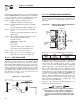
Section 3 — Post Installation Start-up and Adjustments Air-cooled 15 kW Generators 7. Turn utility power to the main distribution panel back on. This can be done by switching the service main breaker to the on or closed position. Allow the generator to shut down. Figure 3.4 — V-twin Full Load Speed Adjust Screw Full Load Speed Adjust Screw not make any unnecessary adjustments. Do Factory settings are correct for most applications.
Section 4 — Operation Air-cooled 15 kW Generators 4.1 USING THE AUTO/OFF/MANUAL SWITCH (FIGURE 4.1) Selecting this switch position activates fully automatic system operation. It also permits starting and exercising of the engine every seven days with the exercise timer (see "Generator Test Under Load"). This position also is used for remote starting, when it is set up. and N2. 3. Set the generator’s AUTO/OFF/MANUAL switch to AUTO. 4.
Section 4 — Operation Air-cooled 15 kW Generators • Retransfer to utility power source then occurs. F. Engine Cool-down Timer • When the load is transferred back to utility power source, the engine cool-down timer starts timing. • The timer will run for about one minute, and the generator will then shut down. 4.4 MANUAL OPERATION 3. Note position of transfer mechanism main contacts by observing the moveable contact carrier arm.
Section 4 — Operation Air-cooled 15 kW Generators 4.4.2 CLOSE TO EMERGENCY SOURCE SIDE Before proceeding, verify the position of the switch by observing the position of the manual operation handle in Figure 4.2. If the handle is DOWN, the contacts are closed in the EMERGENCY (STANDBY) position. No further action is required. If the handle is UP, proceed with Step 1. Step 1: With the handle inserted into the actuating shaft, move the handle DOWN.
Section 4 — Operation Air-cooled 15 kW Generators 7. Move the switch's main contacts back to their UTILITY position. For example, load connected to UTILITY power supply. Refer to "Manual Operation". Handle and operating lever of transfer switch should be in UP position. 8. Turn on the UTILITY power supply to transfer switch, using whatever means provided (such as a UTILITY main line circuit breaker). The UTILITY power source now powers the loads. 9.
Section 5 — Maintenance Air-cooled 15 kW Generators 4.8.3.1 Approximate Crank Cycle Times • • • • • 2. Remove the dipstick and wipe it dry with a clean cloth. 15 seconds ON 7 seconds OFF 7 seconds ON 7 seconds OFF Repeat for 45 seconds Approximately 90 seconds total Figure 5.2 — Oil Dipstick and Fill Oil Dipstick 4.8.4 OVERSPEED Oil Fill This feature protects the generator from damage by shutting it down if it happens to run faster than the preset limit.
Section 5 — Maintenance Air-cooled 15 kW Generators Figure 5.3 – Oil Drain Hose and Filter Figure 5.4 — Engine Air Cleaner Screw Loos en Oil Drain Hose Cover Oil Filter Filter 3. After the oil has drained, replace the cap onto the end of the oil drain hose. Retain the hose in the clip. 4. Refill with the proper recommended oil (see "Changing the Engine Oil"). See the "Specifications" section for oil capacities. 5.4 CHANGING THE OIL FILTER Change the engine oil filter as follows: 1.
Section 5 — Maintenance Air-cooled 15 kW Generators 5.7 BATTERY MAINTENANCE The battery should be inspected per the “Service Schedule”. The following procedure should be followed for inspection: 1. Inspect the battery posts and cables for tightness and corrosion. Tighten and clean as necessary. 2. Check the battery fluid level of unsealed batteries and, if necessary, fill with DISTILLED WATER ONLY. DO NOT USE TAP WATER IN BATTERIES. 3. Have the state of charge and condition checked.
Section 5 — Maintenance Air-cooled 15 kW Generators When valve clearance is correct, hold the pivot ball stud in place with the allen wrench and tighten the rocker arm jam nut. Tighten the jam nut to 174 in/lbs. torque. After tightening the jam nut, recheck valve clearance to make sure it did not change. Figure 5.7 – Cooling Vent Locations Figure 5.6 - Valve Clearance Adjustment Jam Nut Pivot Ball Stud Rocker Arm Valve Stem 5.
Section 5 — Maintenance Air-cooled 15 kW Generators 5.12.2 RETURN TO SERVICE To return the unit to service after storage, proceed as follows: 1. Set the generator’s main circuit breaker to its OFF (or OPEN) position. 2. Verify that utility power is turned off and that the AUTO/OFF/MANUAL switch is set to OFF. 3. Check the tag on the engine for oil viscosity and classification. Verify that the correct recommended oil is used in the engine (see "Enging Oil Requirements").
Section 5 — Maintenance Air-cooled 15 kW Generators 7 KW - 40 KW SMALL STANDBY GENERATOR SETS Following is a recommended maintenance schedule for small standby and residential generator sets from 7 kW to 40 kW in size, and applies to gas engine driven units. The established intervals in the schedule are the maximum recommended when the unit is used in an average service application. They will need to be decreased (performed more frequently) if the unit is used in a severe application.
Section 5 — Maintenance Air-cooled 15 kW Generators Maintenance Tasks 1. Disable the unit from operating per the first page warning. 2. Check the engine oil level. Adjust as necessary. 3. Check the natural gas delivery system for leaks and correct pressure on gas engine driven units. Tighten connections as necessary. 4. Check the air inlets and outlets for debris. Clean as necessary. 5. Check the battery electrolyte level and specific gravity if accessible. Adjust as necessary. 6.
Section 5 — Maintenance Air-cooled 15 kW Generators Maintenance Tasks 10. Test the engine and transfer switch safety devices. Correct and/or adjust as necessary. 11. Initiate an automatic start and transfer of the unit to site load and exercise it for at least 1 hour looking for leaks, loose connections or components, and abnormal operating conditions. Correct as necessary. 12.
Section 5 — Maintenance Air-cooled 15 kW Generators Maintenance Tasks 16. Replace the engine air filter(s). 17. Perform a 5 minute no-load operational run of the unit looking for any post service problems. 18. Return the unit to standby setup for operation when required. 26 Level 1 Recommended to be done monthly/ 10 hrs. Level 2 Level 3 Task Task Required Comp. Comp. to be done (Date- Required (DateSemiInitials) to be done Initials) annually/ 6 months 50 hrs. Level 4 Task Comp.
Section 6 — Troubleshooting Air-cooled 15 kW Generators 6.1 TROUBLESHOOTING GUIDE Problem Cause Correction The engine will not crank. 1. Fuse blown 1. Replace 15A fuse on generator control panel. 2. Tighten, clean or replace as necessary. 3. * 4. Charge or replace battery. 2. Loose, corroded or defective battery cables 3. Defective starter motor 4. Dead Battery The engine cranks but will not start. The engine starts hard and runs rough.
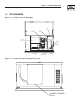
Section 7 — Mounting Dimensions Air-cooled 15 kW Generators Drawing No.
Section 8 — Electrical Data Air-cooled 15 kW Generators Wiring Diagram – Drawing No.
Section 8 — Electrical Data Air-cooled 15 kW Generators Wiring Diagram – Drawing No.
Section 8 — Electrical Data Air-cooled 15 kW Generators Wiring Diagram – Drawing No.
Section 8 — Electrical Data Air-cooled 15 kW Generators Electrical Schematic – Drawing No.
Section 8 — Electrical Data Air-cooled 15 kW Generators Electrical Schematic – Drawing No.
Section 9 — Exploded Views and Parts Lists Air-cooled 15 kW Generators Enclosure – Drawing No.
Section 9 — Exploded Views and Parts Lists Air-cooled 15 kW Generators Enclosure – Drawing No. 0F5845 ITEM PART NO. QTY.
48 36 37 51 49 50 22 8,9 38 53 27 28 19 46 45 44 47 10 25 29 5 15 6 38 7 14 13 4 25 23 27 13 17 12 40 25 20 34 23 43 36 21 39 15 44 45 1 41 35 15 3 11 30 45 47 47 45 24 31 Section 9 — Exploded Views and Parts Lists Air-cooled 15 kW Generators Control Panel – Drawing No.
Section 9 — Exploded Views and Parts Lists Air-cooled 15 kW Generators Control Panel – Drawing No. 0F5846 ITEM 1 2 3 4 5 6 7 8 9 10 11 12 13 14 15 16 17 18 19 20 21 22 23 24 25 26 27 28 29 30 31 32 33 34 35 36 37 38 39 40 41 42 43 44 45 46 47 48 49 50 51 52 PART NO.
Section 9 — Exploded Views and Parts Lists Air-cooled 15 kW Generators GT-990 Engine – Drawing No.
Section 9 — Exploded Views and Parts Lists Air-cooled 15 kW Generators GT-990 Engine – Drawing No. 0E8774-Q Part 1 ITEM PART NO. QTY.
Section 9 — Exploded Views and Parts Lists Air-cooled 15 kW Generators GT-990 Engine – Drawing No.
Section 9 — Exploded Views and Parts Lists Air-cooled 15 kW Generators GT-990 Engine – Drawing No. 0E8774-Q Part 2 ITEM PART NO. QTY.
42 11 23 5 24 21 43 7 34 33 12 39 13 8 4 6 9 31 17 32 31 28 37 38 40 20 3 14 22 2 15 1 19 10 17 32 10 30 19 32 25 16 24 26 29 36 27 28 18 28 35 36 29 41 28 10 42 32 36 31 41 35 36 Section 9 — Exploded Views and Parts Lists Air-cooled 15 kW Generators 15 kW Generator – Drawing No.
Section 9 — Exploded Views and Parts Lists Air-cooled 15 kW Generators 15 kW Generator – Drawing No. 0D3417-L ITEM 1 2 3 4 5 6 7 8 9 10 11 12 13 14 15 16 17 18 19 20 21 22 23 24 25 26 27 28 29 30 31 32 33 34 35 36 37 38 39 40 41 42 43 PART NO. QTY.
Section 9 — Exploded Views and Parts Lists 21 23 22 19 13 13 26 44 11 10 28 12 20 21 25 24 23 22 19 17 32 12 28 10 15 14 11 3 27 31 4 2 5 16 29 18 8 17 1 26 15 14 37 16 9 30 10 7KW 29 18 24 11 25 12 20 28 Air-cooled 15 kW Generators Gas Regulator – Drawing No.
Section 9 — Exploded Views and Parts Lists Air-cooled 15 kW Generators Gas Regulator – Drawing No. 0D8720-H ITEM 1 2 3 4 5 8 9 10 11 12 13 14 15 16 17 18 19 20 21 22 23 24 25 26 27 28 29 30 31 32 37 PART NO. 0D5694 0F5022 0C4647 0D4166 0C6070 0F4795 0C5760J 0C6606 097934 0C4645 0C5761 0C5968 0C6066 0C5759 0C5764 0C5764A 070728 0C6069 0C5762 045764 0C6731 0C6067 0C4706 0C6068 0C4643A 026073 026073 0A4032 0D3308 024310 028414A 0D5698A 0D3973 QTY.
Section 9 — Exploded Views and Parts Lists Air-cooled 15 kW Generators Transfer Switch – Drawing No.
Section 9 — Exploded Views and Parts Lists Air-cooled 15 kW Generators Transfer Switch – Drawing No. 0F5633$-A ITEM PART NO.
Section 10 – Warranty Air-cooled 15 kW Generators NOTE: This Emission Control Warranty Statement pertains to this product only IF the generator size is 15 kW or below. CALIFORNIA EMISSION CONTROL WARRANTY STATEMENT YOUR WARRANTY RIGHTS AND OBLIGATIONS The California Air Resources Board (CARB) and Generac Power Systems, Inc. (Generac) are pleased to explain the Emission Control System Warranty on your new engine.
Section 10 – Warranty Air-cooled 15 kW Generators EMISSION CONTROL SYSTEM WARRANTY Emission Control System Warranty (ECS Warranty) for 1995 and later model year engines: (a) Applicability: This warranty shall apply to 1995 and later model year engines. The ECS Warranty Period shall begin on the date the new engine or equipment is purchased by/delivered to its original, end-use purchaser/owner and shall continue for 24 consecutive months thereafter.
Section 10 – Warranty Air-cooled 15 kW Generators GENERAC POWER SYSTEMS STANDARD LIMITED WARRANTY FOR HOME STANDBY/LIGHT COMMERCIAL PRODUCT 45kW AND BELOW For a period of two (2) years from the date of sale, or start-up by Authorized/Certified Generac Power Systems Dealer, or branch thereof, Generac Power Systems, Inc.