Installation and Owner’s Manual Air-cooled, Prepackaged Automatic Standby Generators Models: 04389-1 (6 kW NG, 7 kW LP) 04456-1 (12 kW NG, 12 kW LP) 04390-1 (13 kW NG, 15 kW LP) GENERAC R POWER SYSTEMS, INC. R ! Not intended for use as Primary Power in place of utility or in life-support applications. DANGER DEADLY EXHAUST FUMES.
INTRODUCTION Thank you for purchasing this model of the Guardian product line by Generac Power Systems Inc. This model is a compact, high performance, air-cooled, engine-driven generator designed to automatically supply electrical power to operate critical loads during a utility power failure. This unit is factory installed in an all-weather, metal enclosure that is intended exclusively for outdoor installation.
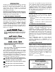
Table of Contents Guardian Air-cooled 7 kW, 12 kW and 15 kW Generators Introduction ........................Inside Front Cover 3.2.2 “Off” Position ....................................14 Read This Manual Thoroughly ........................IFC Contents ..........................................................IFC Operation and Maintenance ............................IFC How to Obtain Service ....................................IFC Authorized Dealer Locator Number ....................IFC 3.2.
IMPORTANT SAFETY INSTRUCTIONS Guardian Air-cooled 7 kW, 12 kW and 15 kW Generators SAVE THESE INSTRUCTIONS – The manufacturer suggests that these rules for safe operation be copied and posted near the unit’s installation site. Safety should be stressed to all operators and potential operators of this equipment. ! ! WARNING: ! GENERAL HAZARDS ! ! The engine exhaust from this product contains chemicals known to the state of California to cause cancer, birth defects or other reproductive harm.
IMPORTANT SAFETY INSTRUCTIONS Guardian Air-cooled 7 kW, 12 kW and 15 kW Generators ELECTRICAL HAZARDS • All generators covered by this manual produce dangerous electrical voltages and can cause fatal electrical shock. Utility power delivers extremely high and dangerous voltages to the transfer switch as does the standby generator when it is in operation. Avoid contact with bare wires, terminals, connections, etc., while the unit is running.
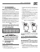
Section 1 — General Information Guardian Air-cooled 7 kW, 12 kW and 15 kW Generators DANGER ! 1.1 Only qualified electricians or contractors should attempt such installations, which must comply strictly with applicable codes, standards and regulations. UNPACKING/INSPECTION After unpacking, carefully inspect the contents for damage. • This standby generator set has been factory supplied with a weather protective enclosure that is intended for outdoor installation only.
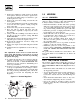
Section 1 — General Information Guardian Air-cooled 7 kW, 12 kW and 15 kW Generators 1.4 YOUR GENERATOR Figure 1.1 – 7 kW, Single Cylinder GH-410 Engine Control Panel Data Decal Exhaust Enclosure Air Filter Fuel Regulator Oil Filter Battery Compartment Figure 1.2 – 12 kW and 15 kW, V-twin GT-990 Engine Oil Dipstick Data Decal Air Filter Control Panel Exhaust Enclosure Fuel Regulator Battery Compartment Oil Filter Generac® Power Systems, Inc.
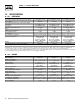
Section 1 — General Information Guardian Air-cooled 7 kW, 12 kW and 15 kW Generators 1.5 SPECIFICATIONS 1.5.1 GENERATOR Rated Max. Continuous Power Capacity (Watts*) Rated Voltage Rated Max.
Section 1 — General Information Guardian Air-cooled 7 kW, 12 kW and 15 kW Generators 1.6 FUEL REQUIREMENTS AND RECOMMENDATIONS With LP gas, use only the vapor withdrawal system. This type of system uses the vapors formed above the liquid fuel in the storage tank. The engine has been fitted with a fuel carburetion system that meets the specifications of the 1997 California Air Resources Board for tamper-proof dual fuel systems.
Section 1 — General Information Guardian Air-cooled 7 kW, 12 kW and 15 kW Generators 3. Remove the small hose clamp and hose from the fuel regulator. It may be necessary to pry the hose off of the brass fitting using a screw driver to gently lift up the hose edge. 4. Remove the brass hose fitting screwed into the fuel regulator. 5. Locate and identify the brass idle jet. This will be located in the fuel regulator casting facing the front of the unit. 6. Remove the idle jet from its holding location. 7.
Section 1 — General Information Guardian Air-cooled 7 kW, 12 kW and 15 kW Generators 1.10 BATTERY INSTALLATION Fill the battery with the proper electrolyte fluid if necessary and have the battery fully charged before installing it. Before installing and connecting the battery, complete the following steps: 1. Set the generator's Auto/Off/Manual switch to OFF. 2. Turn off utility power supply to the transfer switch. 3. Remove the 5A and 15A fuses from the generator control panel.
Section 2 — Post Installation Start-up and Adjustments Guardian Air-cooled 7 kW, 12 kW and 15 kW Generators • Where electrolyte contacts the eyes, flush thoroughly and immediately with water and seek medical attention; and • Spilled electrolyte is to be washed down with an acid neutralizing agent. A common practice is to use a solution of 1 pound (500 grams) bicarbonate of soda to 1 gallon (4 liters) of water.
Section 2 — Post Installation Start-up and Adjustments Guardian Air-cooled 7 kW, 12 kW and 15 kW Generators 10. Connect an accurate AC voltmeter and a frequency meter across transfer switch terminal lugs E1 and E2. Voltage should be 242-252 volts; frequency should read about 61-63 Hertz. 11. Connect the AC voltmeter test leads across terminal lug E1 and neutral; then across E2 and neutral. In both cases, voltage reading should be 121126 volts AC. 12.
Section 2 — Post Installation Start-up and Adjustments Guardian Air-cooled 7 kW, 12 kW and 15 kW Generators 2.6 ADJUSTING THE REGULATOR (NATURAL GAS ONLY) Although the generator has been factory set to provide maximum power, it may be necessary in some areas to adjust this setting. Because natural gas has different BTU or power content across the country the engine may not perform as designed. 6. When the highest frequency is reached maximum power has been set.
Section 2 — Post Installation Start-up and Adjustments Guardian Air-cooled 7 kW, 12 kW and 15 kW Generators 5. Turn the speed adjust nut to obtain a frequency reading of 63 Hz. 6. When frequency is correct at no load, check the AC voltage reading. If voltage is incorrect, the voltage regulator may require adjustment. Figure 2.3 — Engine Governor Adjustment 6. Using a hand, push the governor arm to the closed throttle position. Make sure the idle spring does not stretch at all. 7. Restart the unit. 8.
Section 3 — Operation Guardian Air-cooled 7 kW, 12 kW and 15 kW Generators 3.1 BREAK-IN PROCEDURE Once the unit has been installed and all electrical checks have been made, it is strongly recommended that the following “Break-in Procedure” be completed to ensure correct generator operation in the future. 1. Set the generator’s Auto/Off/Manual switch to AUTO. 2. Turn OFF the utility power supply to the transfer switch using the means provided (such as a utility main line circuit breaker). 3.
Section 3 — Operation Guardian Air-cooled 7 kW, 12 kW and 15 kW Generators 3.4 SEQUENCE OF AUTOMATIC OPERATION The generator’s control panel houses a control logic circuit board. This board constantly monitors utility power source voltage. Should that voltage drop below a preset level, circuit board action will signal the engine to crank and start.
Section 3 — Operation Guardian Air-cooled 7 kW, 12 kW and 15 kW Generators 3.5.2 TRANSFER BACK TO UTILITY POWER SOURCE When utility power has been restored, transfer back to that source and shut down the generator. This can be accomplished as follows: 1. Set the generator’s main circuit breaker to its OFF (or open) position. 2. Let the engine run for a minute or two at no-load to stabilize the internal temperatures. 3. Set the generator’s Auto/Off/Manual switch to its OFF (or open) position.
Section 4 — Maintenance Guardian Air-cooled 7 kW, 12 kW and 15 kW Generators NOTE: If the fault is not repaired, the overcrank feature will continue to activate. 3.7.3.1 Approximate Crank Cycle Times • • • • • 15 seconds ON 7 seconds OFF 7 seconds ON 7 seconds OFF Repeat for 45 seconds Approximately 90 seconds total 3.7.4 OVERSPEED This feature protects the generator from damage by shutting it down if it happens to run faster than the preset limit.
Section 4 — Maintenance Guardian Air-cooled 7 kW, 12 kW and 15 kW Generators 4.3 CHANGING THE ENGINE OIL 4.3.1 ENGINE OIL RECOMMENDATIONS Use oil of American Petroleum Institute (API) Service Class SG, SH or SJ. Use all season SAE 5W-30 Synthetic oil. Organic break-in oil is required before using synthetic oil. NOTE: The unit is supplied with “break-in” oil. See the “Break-in Procedure,” Section 3.1, for the first required oil change.
Section 4 — Maintenance Guardian Air-cooled 7 kW, 12 kW and 15 kW Generators Figure 4.7 — 12 kW and 15 kW Engine Air Cleaner Screw Cover 4.7 BATTERY MAINTENANCE The battery should be inspected per the “Service Schedule,” Section 4.13. The following procedure should be followed for inspection: 1. Inspect the battery posts and cables for tightness and corrosion. Tighten and clean as necessary. 2. Check the battery fluid level of unsealed batteries and, if necessary, fill with Distilled Water Only.
Section 4 — Maintenance Guardian Air-cooled 7 kW, 12 kW and 15 kW Generators Lead-acid batteries present a risk of fire because they generate hydrogen gas. The following procedures are to be followed: • DO NOT SMOKE when near the battery; • DO NOT cause flame or spark in battery area; and • Discharge static electricity from your body before touching the battery by first touching a grounded metal surface.
Section 4 — Maintenance Guardian Air-cooled 7 kW, 12 kW and 15 kW Generators The exhaust from this product gets extremely hot and remains hot after shutdown. High grass, weeds, brush, leaves, etc. must remain clear of the exhaust. Such materials may ignite and burn from the heat of the exhaust system. ! The maximum ambient temperature for the generator is 40° C (104° F). 4.10 ATTENTION AFTER SUBMERSION If the generator has been submerged in water, it MUST NOT be started and operated.
Section 4 — Maintenance Guardian Air-cooled 7 kW, 12 kW and 15 kW Generators 4.13 SERVICE SCHEDULE ATTENTION: It is recommended that all service work be performed by your nearest Generac/Guardian Authorized Dealer. SYSTEM/COMPONENT X = Action R = Replace as Necessary * = Notify Dealer if Repair is Needed.
Section 5 — Troubleshooting Guardian Air-cooled 7 kW, 12 kW and 15 kW Generators 5.1 TROUBLESHOOTING GUIDE PROBLEM CAUSE The engine will not crank. 1. Fuse blown. 2. 3. 4. 5. The engine cranks but will not start. The engine starts hard and runs rough. The Auto/Off/Manual switch is set to OFF, but the engine continues to run. There is no AC output from the generator. CORRECTION 1. Replace 15A fuse in generator control panel. Loose, corroded or defective 2.
Section 6 — Electrical Data Guardian Air-cooled 7 kW, 12 kW and 15 kW Generators Wiring Diagram – 12 & 15 kW – Drawing No.
Section 6 — Electrical Data Guardian Air-cooled 7 kW, 12 kW and 15 kW Generators Wiring Diagram – 12 & 15 kW – Drawing No.
Section 6 — Electrical Data Guardian Air-cooled 7 kW, 12 kW and 15 kW Generators Electrical Schematic – 12 & 15 kW – Drawing No.
Section 6 — Electrical Data Guardian Air-cooled 7 kW, 12 kW and 15 kW Generators Electrical Schematic – 12 & 15 kW – Drawing No.
Section 6 — Electrical Data Guardian Air-cooled 7 kW, 12 kW and 15 kW Generators Wiring Diagram – 7 kW – Drawing No.
Section 6 — Electrical Data Guardian Air-cooled 7 kW, 12 kW and 15 kW Generators Wiring Diagram – 7 kW – Drawing No.
Section 6 — Electrical Data Guardian Air-cooled 7 kW, 12 kW and 15 kW Generators Electrical Schematic – 7 kW – Drawing No.
Section 6 — Electrical Data Guardian Air-cooled 7 kW, 12 kW and 15 kW Generators Electrical Schematic – 7 kW – Drawing No.
Section 7 — Exploded Views and Parts Lists Guardian Air-cooled 7 kW, 12 kW and 15 kW Generators Enclosure – Drawing No.
Section 7 — Exploded Views and Parts Lists Guardian Air-cooled 7 kW, 12 kW and 15 kW Generators Enclosure – Drawing No. 0D3416-Q ITEM PART NO.QTY.
Section 7 — Exploded Views and Parts Lists 31 30 35 3 23 16 34 17 13 17 4 19 45 44 47 27 0 38 37 7 22 46 14 15 2 48 29 28 35 6 38 7 16 23 27 8 32 8,9 34 Generac® Power Systems, Inc. 5 15 14 36 12 3 40 15 20 49 43 13 45 44 42 39 1 41 11 14 47 45 24 45 31 47 Guardian Air-cooled 7 kW, 12 kW and 15 kW Generators Control Panel – Drawing No.
Section 7 — Exploded Views and Parts Lists Guardian Air-cooled 7 kW, 12 kW and 15 kW Generators Control Panel – Drawing No. 0D8503-F ITEM PART NO. QTY.
Section 7 — Exploded Views and Parts Lists Guardian Air-cooled 7 kW, 12 kW and 15 kW Generators 7 kW GTS Load Center Assembly – Drawing No. 0D3997-E 31 37 7 9 17 11 5 2 18 3A 29 36 24 10 22 16 30 9 27 15 13 1 3 19 25 3B 22 40 12 16 21 23 26 14 38 33 32 8 34 35 34 36 Generac® Power Systems, Inc.
Section 7 — Exploded Views and Parts Lists Guardian Air-cooled 7 kW, 12 kW and 15 kW Generators 7 kW GTS Load Center Assembly – Drawing No. 0D3997-E ITEM 1 2 3 3A 3B 3C 3D 4 5 6 7 8 9 10 11 12 13 14 15 16 17 18 19 21 22 23 24 25 26 27 28 29 30 31 32 33 34 35 36 37 38 39 40 PART NO.
Section 7 — Exploded Views and Parts Lists Guardian Air-cooled 7 kW, 12 kW and 15 kW Generators 12 kW and 15 kW GTS Load Center Assembly – Drawing No. 0D3996-D 12 31 37 7 9 17 6 11 5 2 18 3A 22 16 30 9 36 24 10 27 15 13 1 3 19 25 3B 22 40 42 16 21 23 26 14 38 41 8 33 35 32 34 34 38 Generac® Power Systems, Inc.
Section 7 — Exploded Views and Parts Lists Guardian Air-cooled 7 kW, 12 kW and 15 kW Generators 12 kW and 15 kW GTS Load Center Assembly – Drawing No. 0D3996-D ITEM 1 2 3 3A 3B 3C 3D 4 5 6 7 8 9 10 11 12 13 14 15 16 17 18 19 21 22 23 24 25 26 27 28 29 30 31 32 33 34 35 36 37 38 39 40 41 42 PART NO.
40 Generac® Power Systems, Inc.
Section 7 — Exploded Views and Parts Lists Guardian Air-cooled 7 kW, 12 kW and 15 kW Generators GT-990 Engine – Drawing No. 0D8674-E Part 1 ITEM PART NO. QTY.
Section 7 — Exploded Views and Parts Lists Guardian Air-cooled 7 kW, 12 kW and 15 kW Generators GT-990/760 Engine – Drawing No. 0D8674-E Part 2 74 138 75 122 124 76 139 125 135 136 123 77 137 120 125 79 24 133 78 132 134 119 80 11 116 127 121 81 118 97 98 130 82 128 29 126 99 96 95 83 102 84 87 86 85 88 89 94 103 109 105 104 141 99 106 112 90 110 101 89 91 92 107 112 112 113 111 42 Generac® Power Systems, Inc.
Section 7 — Exploded Views and Parts Lists Guardian Air-cooled 7 kW, 12 kW and 15 kW Generators GT-990/760 Engine – Drawing No. 0D8674-E Part 2 ITEM PART NO. QTY.
Section 7 — Exploded Views and Parts Lists 14 32 31 28 11 23 5 33 31 53 7 21 51 52 39 12 13 4 6 8 9 31 37 17 38 40 34 46 45 30 3 20 47 2 22 15 36 1 1 10 17 10 30 19 5 34 32 24 16 26 35 44 34 48 28 27 28 18 28 31 32 Guardian Air-cooled 7 kW, 12 kW and 15 kW Generators 7 kW Generator – Drawing No. 0D3504-C 44 Generac® Power Systems, Inc.
Section 7 — Exploded Views and Parts Lists Guardian Air-cooled 7 kW, 12 kW and 15 kW Generators 7 kW Generator – Drawing No. 0D3504-C ITEM PART NO. QTY.
Section 7 — Exploded Views and Parts Lists 28 27 28 17 13 11 2 5 24 43 7 21 34 12 33 39 6 8 31 37 32 31 28 40 38 3 20 14 2 22 15 19 10 17 32 10 19 32 30 25 24 16 26 29 35 18 36 29 10 41 31 32 42 41 Guardian Air-cooled 7 kW, 12 kW and 15 kW Generators 12 kW and 15 kW Generator – Drawing No. 0D3417-D 46 Generac® Power Systems, Inc.
Section 7 — Exploded Views and Parts Lists Guardian Air-cooled 7 kW, 12 kW and 15 kW Generators 12 kW and 15 kW Generator – Drawing No. 0D3417-D ITEM 1 2 3 4 5 6 7 8 9 10 11 12 13 14 15 16 17 18 19 20 21 22 23 24 25 26 27 28 29 30 31 32 33 34 35 36 37 38 39 40 41 42 43 PART NO. QTY.
Section 7 — Exploded Views and Parts Lists 42 17 50 31 25 30 29 28 27 37 24 35 36 23 33 45 43 39 19 18 20 34 46 44 11 32 22 48 47 26 41 38 40 51 25 21 13 14 15 53 49 1 6 54 16 52 1 2 5 10 4 3 7 11 8 9 Guardian Air-cooled 7 kW, 12 kW and 15 kW Generators GN410 Engine – Drawing No. 0D3539-D Part 1 48 Generac® Power Systems, Inc.
Section 7 — Exploded Views and Parts Lists Guardian Air-cooled 7 kW, 12 kW and 15 kW Generators GN410 Engine – Drawing No. 0D3539-D Part 1 ITEM 1 2 3 4 5 6 7 8 9 10 11 12 13 14 15 16 17 18 19 20 21 22 23 24 25 26 27 28 29 30 31 32 33 34 35 36 37 38 39 40 41 42 43 44 45 46 47 48 49 50 51 52 53 54 PART NO.
Section 7 — Exploded Views and Parts Lists 35 34 2 50 Generac® Power Systems, Inc. 6 12 7 19 6 20 6 41 21 40 3 40 5 38 6 28 14 16 1 17 18 13 8 29 44 31 24 30 10 9 11 27 18 18 34 33 2 36 37 4 6 Guardian Air-cooled 7 kW, 12 kW and 15 kW Generators GN410 Engine – Drawing No.
Section 7 — Exploded Views and Parts Lists Guardian Air-cooled 7 kW, 12 kW and 15 kW Generators GN410 Engine – Drawing No. 0D3539-D Part 2 ITEM 1 2 3 4 5 6 7 8 9 10 11 12 13 14 15 16 17 18 19 20 21 22 23 24 25 26 27 28 29 30 31 32 33 34 35 36 37 38 39 40 41 42 43 44 PART NO.
Section 7 — Exploded Views and Parts Lists Guardian Air-cooled 7 kW, 12 kW and 15 kW Generators Gas Regulator – Drawing No. 0D8720-B 10 8 7 34 33 2 6 36 21 5 10 20 37 32 4 37 3 25 24 23 10 1 22 35 FOR GT 760 ENGINE ONLY 19 16 26 29 18 15 14 12 11 28 17 19 13 27 31 32 12 23 22 26 15 14 11 25 29 18 20 16 17 28 24 13 9 21 ITEM 1 2 3 4 5 6 7 8 9 10 11 12 13 14 15 16 17 18 19 20 PART NO. QTY.
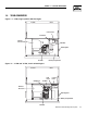
716 [28 743 [29 M6PEM M6P M6PEM-T PE T LEFT SIDE VIEW 622 [24.5"] 604 [23.5"] 76.2mm [3.00"] PEA GRAVEL MINUMUM 704 [27.7"] 207 [8.14"] TRANSFER SWITCH (IF SUPPLIED) 308 [12"] FRONT VIEW 1232 [48.5"] 1193 [47"] "DO NOT LIFT BY THE ROOF" LIFTING HOLES 4-CORNERS Ø30.2mm [Ø1.19"] 149 [5.9"] RIGHT SIDE VIEW 490.7 [ AIR 260 [10.2"] **ALL DIMENSIONS IN: MILLIMETERS [INCHES] REAR VIEW ROUNDING LUG CABLE ACCESS HOLES.
Section 9 — Notes Guardian Air-cooled 7 kW, 12 kW and 15 kW Generators 54 Generac® Power Systems, Inc.
Section 9 — Notes Guardian Air-cooled 7 kW, 12 kW and 15 kW Generators Generac® Power Systems, Inc.
Section 10 – Warranty Guardian Air-cooled 7 kW, 12 kW and 15 kW Generators NOTE: This Emission Control Warranty Statement pertains to this product only IF the generator size is 15 kW or below. CALIFORNIA EMISSION CONTROL WARRANTY STATEMENT YOUR WARRANTY RIGHTS AND OBLIGATIONS The California Air Resources Board (CARB) and Generac Power Systems, Inc. (Generac) are pleased to explain the Emission Control System Warranty on your new engine.
Section 10 – Warranty Guardian Air-cooled 7 kW, 12 kW and 15 kW Generators EMISSION CONTROL SYSTEM WARRANTY Emission Control System Warranty (ECS Warranty) for 1995 and later model year engines: (a) Applicability: This warranty shall apply to 1995 and later model year engines. The ECS Warranty Period shall begin on the date the new engine or equipment is purchased by/delivered to its original, end-use purchaser/owner and shall continue for 24 consecutive months thereafter.
Section 10 – Warranty Guardian Air-cooled 7 kW, 12 kW and 15 kW Generators GENERAC POWER SYSTEMS STANDARD "TWO YEAR" LIMITED WARRANTY FOR GUARDIAN “EMERGENCY AUTOMATIC STANDBY GENERATORS” For a period of two years from the date of original sale, Generac Power Systems, Inc.