Installation and Owner’s Manual Liquid-cooled, Prepackaged Standby Generators Model Number 004917-2 27 kW NG, 30 kW LP Vapor This manual should remain with the unit. ! Not intended for use in life-support applications. ! DANGER DEADLY EXHAUST FUMES.
INTRODUCTION Thank you for purchasing this model of the standby generator set product line by Generac Power Systems. Every effort was expended to make sure that the information and instructions in this manual are both accurate and current at the time the manual was written. However, the manufacturer reserves the right to change, alter or otherwise improve this product(s) at any time without prior notice.
Table of Contents QUIETSOURCE™ Liquid-cooled 30 kW Generators INTRODUCTION ................................................IFC SAFETY RULES ....................................................2 Section 3 — OPERATION ................................12 3.1 Using a Standard “GTS” Transfer Switch............12 3.2 Control Console Components..............................13 Section 1 — GENERAL INFORMATION ............4 3.3 Manual Transfer and Startup ..............................14 1.1 Generator ......
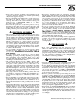
IMPORTANT SAFETY INSTRUCTIONS QUIETSOURCE™ Liquid-cooled 30 kW Generators ! SAVE THESE INSTRUCTIONS – The manufacturer suggests that these rules for safe operation be copied and posted in potential hazard areas. Safety should be stressed to all operators, potential operators, and service and repair technicians for this equipment. ! SAVE THESE INSTRUCTIONS – This manual contains important instructions that should be followed during installation and maintenance of the generator and batteries.
IMPORTANT SAFETY INSTRUCTIONS QUIETSOURCE™ Liquid-cooled 30 kW Generators • Inspect the generator regularly, and promptly repair or replace all worn, damaged or defective parts using only factory-approved parts. • Before performing any maintenance on the generator, disconnect its battery cables to prevent accidental start-up. Disconnect the cable from the battery post indicated by a NEGATIVE, NEG or (–) first. Reconnect that cable last. • Never use the generator or any of its parts as a step.
Section 1 - General Information QUIETSOURCE™ Liquid-cooled 30 kW Generators 1.1 GENERATOR 1.3 This equipment is a liquid-cooled, engine-driven generator set. The generator is designed to supply electrical power that operates critical electrical loads during utility power failure. The unit has been factory-installed in a weather resistant, all aluminum enclosure and is intended for outdoor installation only.
Section 1 - General Information QUIETSOURCE™ Liquid-cooled 30 kW Generators 1.6 NOTE: GENERATOR FUEL SYSTEM The unit has been factory tested and adjusted using a natural gas fuel system. If propane (LP) gas is necessary. Refer to Section 1.11, Fuel Consumption. The Low Oil Pressure, High Coolant Temperature and Low Coolant Level are not monitored for the first 10 seconds of engine run time. Fuel pressure for a natural gas set up should be five inches to 14 inches of water column (0.18 to 0.
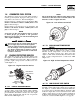
Section 1 — General Information QUIETSOURCE™ Liquid-cooled 30 kW Generators Figure 1.6 - Low Coolant Level Sensor 1.7.7 LOW BATTERY The engine control board continually monitors the battery voltage and turns on the low battery LED if the battery voltage falls below 11.0 VDC for one minute. Low battery voltage is a non-latching alarm, which will automatically clear if the battery voltage rises above 11.0 VDC. 1.7.
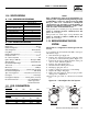
Section 1 — General Information QUIETSOURCE™ Liquid-cooled 30 kW Generators NOTE: 1.10 SPECIFICATIONS 1.10.1 GENERATOR SPECIFICATIONS Single-phase 4917-0 27 (NG), 30 (LP) Model Rated Max. Cont. AC Power Output (kW) Rated voltage (volts) 120/240 No. of Rotor Poles 4 Driven Speed of Rotor 1800 Rotor Excitation System Direct excited brush type Type of Stator 4 Wire Rotor/Stator Insulation Class F/H 1.10.2 ENGINE SPECIFICATIONS Make .......................................................................
Section 2 — Installation QUIETSOURCE™ Liquid-cooled 30 kW Generators NOTE: Port 1 is for NG only and Port 2 is for LP vapor only. No provision for dual fuel has been made. DANGER ! ! Serious injury or damage may occur if not configured properly. Please consult an authorized Generac Service Dealer with any questions. 1.13 TORQUE SPECIFICATIONS Cylinder Head ............................................15 (+ 90° + 90°) ft.lb. Intake Manifold ...............................................................
Section 2 — Installation QUIETSOURCE™ Liquid-cooled 30 kW Generators Only qualified, competent installation contractors or electricians thoroughly familiar with applicable codes, standards and regulations should install this standby electric power system. The installation must comply strictly with all codes, standards and regulations pertaining to the installation.
Section 2 — Installation QUIETSOURCE™ Liquid-cooled 30 kW Generators Figure 2.1 – Basic Standby Electric System 2.7 GROUNDING THE GENERATOR The National Electrical Code requires the frame and external electrically conductive parts of this equipment to be properly connected to an approved earth ground and/or grounding rods. For that purpose, a GROUND LUG (Figure 2.2) is provided on the generator mounting base. Consult a qualified electrician for grounding requirements in the area.
Section 2 — Installation QUIETSOURCE™ Liquid-cooled 30 kW Generators Setting switch two to OFF allows the control PCB to perform the ATS control functions. ! Control system interconnections consist of N1 and N2, and leads 23 and 194. Control system interconnection leads must be run in a conduit that is separate from the AC power leads.
Section 3 — Operation QUIETSOURCE™ Liquid-cooled 30 kW Generators When using maintenance-free batteries, it is not necessary to check the specific gravity or electrolyte level. Have these procedures performed at the intervals specified in Section 4, “Maintenance.” A negative ground system is used. Battery connections are shown on the wiring diagrams. Make sure all batteries are correctly connected and terminals are tight. Observe battery polarity when connecting batteries to the generator set.
Section 3 - Operation QUIETSOURCE™ Liquid-cooled 30 kW Generators • The control board will NOT activate the transfer output. • The control board WILL monitor all engine conditions and shut down on all the faults listed in this document. Pos2 OFF — ATS Application • The control board will perform all of the automatic features listed in this document. • The two-wire start connections should NOT be used. 3.2.
Section 3 — Operation QUIETSOURCE™ Liquid-cooled 30 kW Generators 3.2.6 SYSTEM READY LED The System Ready LED (green) has two main proposes. First, the LED will be ON when the AUTO/OFF/MANUAL switch is in the AUTO position, utility is present, and there are no system alarms. This ON state indicates the system is fully ready for automatic operation. 6. Adjust differential pot to make the recovery to load changes even faster and minimize load change undershoot and overshoot.
Section 4 — Maintenance QUIETSOURCE™ Liquid-cooled 30 kW Generators 3.6 AUTOMATIC OPERATION Figure 3.2 - “Set Exercise” Switch E F E US If a failure occurs while running in this mode, the five red LEDs will stop flashing, the individual fault LED will turn on and the engine will shut down. Once the AUTO/OFF/MANUAL switch has been switch to OFF, the individual fault LED will turn OFF and the five red LEDs will begin flashing to show exercise has still not been set.
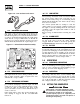
Section 4 — Maintenance QUIETSOURCE™ Liquid-cooled 30 kW Generators 4.2 COOLING SYSTEM Figure 4.1 - Oil Dipstick and Oil Fill Cap Air intake and outlet openings in the generator compartment must be open and unobstructed for continued proper operation. This includes such obstructions as high grass, weeds, brush, leaves and snow. OIL DIPSTICK Without sufficient cooling and ventilating air flow, the engine/generator quickly overheats, which causes it to shut down.
Section 4 — Maintenance QUIETSOURCE™ Liquid-cooled 30 kW Generators 4.5.4 INSPECT COOLING SYSTEM • Inspect engine cooling system at least once each month. • Check hoses for damage, deterioration, leaks, etc. Correct any discrepancies found. • Check hose clamps for tightness. 4.5.5 CHECK ENGINE COOLANT LEVEL See “Checking Fluid Levels” in Section 4.4. 4.5.6 PERFORM VISUAL INSPECTION Complete a thorough visual inspection of the entire engine-generator monthly.
Section 4 — Maintenance QUIETSOURCE™ Liquid-cooled 30 kW Generators Figure 4.3 – Engine Air Cleaner 4.6 MISCELLANEOUS MAINTENANCE 4.6.1 CLEANING THE GENERATOR Keep the generator as clean and as dry as possible. Dirt and moisture that accumulates on internal generator windings have an adverse effect on insulation resistance. Periodically clean generator exterior surfaces. A soft brush may be used to loosen caked on dirt.
Section 4 — Maintenance QUIETSOURCE™ Liquid-cooled 30 kW Generators 4.6.3 BATTERY MAINTENANCE The battery should be inspected per the “Service Schedule,” Section 6. The following procedure should be followed for inspection: 1. Inspect the battery posts and cables for tightness and corrosion. Tighten and clean as necessary. 2. Check the battery fluid level of unsealed batteries and, if necessary, fill with DISTILLED WATER ONLY. DO NOT USE TAP WATER IN BATTERIES. 3.
Section 4 — Maintenance QUIETSOURCE™ Liquid-cooled 30 kW Generators 4.7 SCHEDULED MAINTENANCE Following is a recommended maintenance schedule for Generac small standby and residential generator sets. The established intervals in the schedule are the maximum recommended when the unit is used in an average service application. They will need to be decreased (performed more frequently) if the unit is used in a severe application.
Section 4 — Maintenance QUIETSOURCE™ Liquid-cooled 30 kW Generators Maintenance Tasks Level 1 Recommended to be done monthly Level 2 Task Comp. (DateInitials) Required to be done 3 months/ Break-in Level 3 Task Comp. (DateInitials) Required to be done Semiannually Level 4 Task Comp. (DateInitials) Required to be done Annually Task Comp. (DateInitials) 1. Disable the unit from operating per the first page warning. 2. Check the engine oil level. Adjust as necessary. 3.
Section 4 — Maintenance QUIETSOURCE™ Liquid-cooled 30 kW Generators Maintenance Tasks Level 1 Recommended to be done monthly 13. Initiate an automatic start and transfer of the unit to site load and exercise it for at least 1 hour looking for leaks, loose connections or components, and abnormal operating conditions. Correct as necessary. 14.
Section 5 — Troubleshooting QUIETSOURCE™ Liquid-cooled 30 kW Generators TROUBLESHOOTING POINTS PROBLEM CAUSE CORRECTION Engine won’t crank. 1. 15 amp fuse blown. 2. Loose or corroded or defective battery cables. 3. Defective starter contactor. 4. Defective starter motor. 5. Dead or Defective Battery. 6. 4 amp fuse blown. 1. Replace fuse. 2. Tighten, clean or replace battery cables as necessary. 3. Replace contactor. 4. Replace starter motor. 5. Remove, change or replace battery. 6. Replace fuse.
Section 6 - Electrical Data QUIETSOURCE™ Liquid-cooled 30 kW Generators Wiring Diagram — Engine — Drawing No.
Section 6 - Electrical Data QUIETSOURCE™ Liquid-cooled 30 kW Generators Wiring Diagram — Engine — Drawing No.
Section 6 - Electrical Data QUIETSOURCE™ Liquid-cooled 30 kW Generators Electrical Schematic — Engine — Drawing No. 0E6200-A ALTERNATOR ROTOR ALTERNATOR STATOR AUTOMATIC VOLTAGE REGULATOR BRUSH ASSEMLY (GENERATOR) BATTERY CHARGER BATTERY CAHRGE WINDING CIRCUIT BREAKER (OUTPUT) CIRCUIT BREAKER (EXCITATION) DIODE [FIELD BOOST] DISPLACED PHASE EXCITATION LEGEND {CONT.]: F1 FUSE, BAT. POWER (15A AGC TYPE) F2 FUSE, B/C (4A AGC TYPE) ICT TERMINAL BLOCK, INTERCONNECT.
Section 6 - Electrical Data QUIETSOURCE™ Liquid-cooled 30 kW Generators Electrical Schematic — Engine — Drawing No.
16 28 Generac® Power Systems, Inc. 7 6 5 2 4 3 ENGINE FOOT 12 13 17 9 35 18 16 8 40 3 36 30 16 43 44 TO ENGINE BLOCK 34 35 41 38 18 44 32 33 22 42 20 31 20 7 6 5 37 15 1 13 14 12 11 REAR BEARING CARRIER HARNESS WIRE TO STARTER CONTACTOR TO STARTER BOLT TO ENGINE 18 BLOCK 14 16 10 4 3 2 Section 7 - Exploded Views and Parts QUIETSOURCE™ Liquid-cooled 30 kW Generators Mounting Base — Drawing No.
Section 8 - Exploded Views and Parts QUIETSOURCE™ Liquid-cooled 30 kW Generators Mounting Base — Drawing No. 0E6266-E ITEM 1 2 3 4 5 6 7 8 9 10 11 12 13 14 15 16 17 18 20 21 22 23 * 24 * 25 * 26 * 30 31 32 33 34 35 36 37 38 39 40 41 42 43 44 PART NO.
30 Generac® Power Systems, Inc. 3 30 31 LATCH DETAIL 38 1 32 34 18 17 45 27 2 41 4 37 4 35 53 25 RADIATOR 33 4 STATES FOAM IS ON FAR SIDE STATES FOAM IS ON NEAR SIDE 53 46 4 4 4 13 9 11 SEE LATCH DETAIL 26 TO "A" TYPICAL OF ROOF PANEL THAT REQUIRE INSULATION. SECURE AS SHOWN.
Section 7 - Exploded Views and Parts QUIETSOURCE™ Liquid-cooled 30 kW Generators Compartment — Drawing No. 0E8519-B ITEM 1 2 3 4 5 6 7 8 9 10 11 12 13 14 15 16 17 18 19 20 21 22 23 24 25 26 27 28 29 30 31 32 33 34 35 36 37 38 39 40 41 42 43 44 45 46 50 * 51 52 53 54 55 56 57 58 59 PART NO.
Section 7 - Exploded Views and Parts QUIETSOURCE™ Liquid-cooled 30 kW Generators Control Panel — Drawing No. 0E7118-G 32 Generac® Power Systems, Inc.
Section 7 - Exploded Views and Parts QUIETSOURCE™ Liquid-cooled 30 kW Generators Control Panel — Drawing No. 0E7118-G ITEM PART NO. QTY. 1 2 3 4 5 6 7 8 9 10 11 12 13 14 15 16 0E7195 0E7196 0E7197 0E7193 0E7194 0E4494 082573 032300 022676 067682B 060015 054199 0C2657 099076 040213 0E9668 0E4905 1 1 1 1 1 1 1 2 1 1 1 1 1 1 2 1 1 17 18 19 20 21 067680 0E6875A 0E6881 * 0C5139 * 0E5142 * 1 1 REF. REF. REF.
Section 7 - Exploded Views and Parts QUIETSOURCE™ Liquid-cooled 30 kW Generators Engine — Drawing No. 0E8170-J 69 27 28 57 58 14 1 15 60 10 8 25 61 36 35 38 42 2 55 43 47 51 54 36 3 42 35 34 36 43 35 7 42 40 36 35 3 37 6 78 12 5 BAFFLE REAR UPPER 21 43 11 47 38 26 7 73 29 2 57 31 58 60 48 44 30 61 24 36 35 39 25 31 32 48 17 39 45 35 64 42 65 41 66 68 GROUND WIRE 79 34 Generac® Power Systems, Inc.
Section 7 - Exploded Views and Parts QUIETSOURCE™ Liquid-cooled 30 kW Generators Engine — Drawing No. 0E8170-J ITEM PART NO. QTY.
Section 7 - Exploded Views and Parts 15 FRAME 9 8 3 36 Generac® Power Systems, Inc. 11 10 9 12 "A" 27 20 15 1 4 21 3 12 TO WATER PUMP 24 22 24 2 6 17 7 12 TO ENGINE 5 13 12 18 14 TO "A" QUIETSOURCE™ Liquid-cooled 30 kW Generators Radiator — Drawing No.
Section 7 - Exploded Views and Parts QUIETSOURCE™ Liquid-cooled 30 kW Generators Radiator — Drawing No. 0E8528-B ITEM 1 2 3 4 5 6 7 8 9 10 11 12 13 14 15 17 18 20 21 22 23 24 25 26 27 PART NO. 0E9947 0E6340 0E8531 0E6398 0E6397 080713 076749 049814 022131 046526 045772 035685 0E8562 058443 0C2454 048031C 029032 046627 069811 065852 0A2111 052250 035461 0C7649 069860C QTY. 1 1 2 1 1 1 1 4 8 4 4 4 1 4 9 1 1 1 1 1 1 2 1 1 1 DESCRIPTION RADIATOR R-IN,L-OUT 658X489X49 VENTURI 3.
Section 7 - Exploded Views and Parts 15 38 Generac® Power Systems, Inc. 5 16 2 4 10 29 32 30 29 11 17 6 1 7 9 31 29 6 8 3 ANER 13 18 26 27 19 "B" 2 21 39 QUIETSOURCE™ Liquid-cooled 30 kW Generators Fuel System — Drawing No.
Section 7 - Exploded Views and Parts QUIETSOURCE™ Liquid-cooled 30 kW Generators Fuel System — Drawing No. 0E8190-B ITEM PART NO. 1* 2 3 4 5 6 7 8 9 10 11 12 13 14 15 16 17 18 19 20 21 25 26 27 28 29 30 31 32 33 34 35 ** 36 ** 37 ** 38 ** 39 --------075580 0E7691 039253 022145 022129 045771 042907 0C2454 026307 0E1056 0E6584 057823 059194 044117 0D1509 050279 0E6123 0E6586 0E4395 057753B 047487 022097 051751 035685 057823 047290 047290 0A4121 0E6609 049099 055934M 047411 022097 O22473 0E9295A QTY.
Section 7 - Exploded Views and Parts 12 15 7 17 4 1 18 31 30 5 LEADS 2 6 7 9 21 8 3 10 11 * 20 19 14 QUIETSOURCE™ Liquid-cooled 30 kW Generators Alternator — Drawing No. 0E8660-B 40 Generac® Power Systems, Inc.
Section 7 - Exploded Views and Parts QUIETSOURCE™ Liquid-cooled 30 kW Generators Alternator — Drawing No. 0E8660-B ITEM PART NO. QTY.
Section 7 - Exploded Views and Parts QUIETSOURCE™ Liquid-cooled 30 kW Generators Muffler — Drawing No. 0E8766-B 2 11 18 1 19 17 16 7 8 16 16 17 20 18 19 8 TO COMPARTMENT 15 16 TO MANIFOLD 11 22 17 10 4 11 21 6 11 12 TO MANIFOLD 3 22 17 4 10 14 21 12 5 9 13 14 ITEM PART NO. QTY. 1 0E8616 1 2 3 4 5 6 7 0E8727 0E8822 0E8821 0E6465 0E6465A 0E5914 1 1 2 1 1 1 8 9 0E8726 0E0170A 2 2 036797 2 10 DESCRIPTION MUFFLER 7" X 9" X 21" 2.
Section 7 - Exploded Views and Parts QUIETSOURCE™ Liquid-cooled 30 kW Generators Air Cleaner — Drawing No. 0E8189 ITEM PART NO. QTY. 1 2 3 4 5 0E5193 0E8200 0E8201 036434 0E0519A 1 1 1 1 1 6 7 8 9 10 0C8127 0A5547 062974 022127 037561 1 1 1 1 1 DESCRIPTION PLATE AIR CLEANER ADAPTER TUBE AIR INTAKE 3.0L FORD BRACKET AIR INTAKE 3.0L FORD BOLT U 5/16-18 X 2.
Section 8 — Installation Diagram QUIETSOURCE™ Liquid-cooled 30 kW Generators Installation Diagram — Drawing No. 0E8696 44 Generac® Power Systems, Inc.
Section 9 — Notes QUIETSOURCE™ Liquid-cooled 30 kW Generators Generac® Power Systems, Inc.
Section 10 – Warranty QUIETSOURCE™ Liquid-cooled 30 kW Generators GENERAC POWER SYSTEMS "TWO YEAR" LIMITED WARRANTY FOR QUIETSOURCE™ "PREPACKAGED EMERGENCY AUTOMATIC STANDBY GENERATORS" For a period of two years from the date of original sale, Generac Power Systems, Inc. (Generac) warrants that its Quietsource generator will be free from defects in material and workmanship for the items and period set forth below.