Installation and Owner’s Manual Air-cooled, Prepackaged Automatic Standby Generators Model No. 004916-0 (10 kW NG, 11 kW LP) *This manual should remain with the unit. as Primary Power in place of utility or in Not intended for use life-support applications. DANGER DEADLY EXHAUST FUMES.
INTRODUCTION Thank you for purchasing this model of the Quiet Source product line by Generac Power Systems Inc. This model is a compact, high performance, aircooled, engine-driven generator designed to automatically supply electrical power to operate critical loads during a utility power failure. This unit is factory installed in an all-weather, metal enclosure that is intended exclusively for outdoor installation.
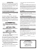
Table of Contents Air-cooled 11 kW Generators Introduction ............................... Inside Front Cover Section 3 – Operation ........................................... 11 Read This Manual Thoroughly ................................. IFC 3.1 Break-in Procedure ............................................. 11 Contents .................................................................. IFC 3.2 Using the AUTO/OFF/MANUAL Switch ................ 11 Operation and Maintenance .......................
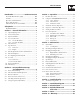
IMPORTANT SAFETY INSTRUCTIONS Air-cooled 11 kW Generators SAVE THESE INSTRUCTIONS – The manufacturer suggests that these rules for safe operation be copied and posted near the unit’s installation site. Safety should be stressed to all operators and potential operators of this equipment. WARNING: The engine exhaust from this product contains chemicals known to the state of California to cause cancer, birth defects or other reproductive harm.
IMPORTANT SAFETY INSTRUCTIONS Air-cooled 11 kW Generators ELECTRICAL HAZARDS • All generators covered by this manual produce dangerous electrical voltages and can cause fatal electrical shock. Utility power delivers extremely high and dangerous voltages to the transfer switch as does the standby generator when it is in operation. Avoid contact with bare wires, terminals, connections, etc., while the unit is running.
Section 1 — General Information Air-cooled 11 kW Generators DANGER qualified electricians or contractors should Only attempt such installations, which must comply strictly with applicable codes, standards and regulations. 1.1 UNPACKING/INSPECTION After unpacking, carefully inspect the contents for damage. • This standby generator set has been factory supplied with a weather protective enclosure that is intended for outdoor installation only.
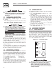
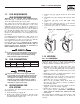
Section 1 — General Information Air-cooled 11 kW Generators 1.4.2 120 VOLT AC OUTLET Figure 1.2 — 120 Volt AC Outlet The generator is equipped with an external, 15 amp, 120 volt, GFCI convenience outlet located on the front of the unit (Figure 1.2). When the generator is running, in the absence of utility power, this outlet may be used to power items outside the home such as lights or power tools. This outlet may also be used when utility power is present by running the generator in manual mode.
Section 1 — General Information Air-cooled 11 kW Generators 1.6 SPECIFICATIONS 1.6.1 GENERATOR Rated Max. Continuous Power Capacity (Watts*) Rated Voltage Rated Max. Continuous Load Current (Amps) 120 Volts** 240 Volts Main Line Circuit Breaker Phase Number of Rotor Poles Rated AC Frequency Power Factor Recommended Air Filter Battery Requirement at -17.8° C (0° F) Weight Output Sound Level @ 23 ft (7m) at full load Normal Operating Range Model 04916-0 10,000 NG/11,000 LP 120/240 83.3 NG/91.7 LP 41.
Section 1 — General Information Air-cooled 11 kW Generators 1.7 FUEL REQUIREMENTS AND RECOMMENDATIONS With LP gas, use only the vapor withdrawal system. This type of system uses the vapors formed above the liquid fuel in the storage tank. The engine has been fitted with a fuel carburetion system that meets the specifications of the 1997 California Air Resources Board for tamper-proof dual fuel systems. The unit will run on natural gas or LP gas, but it has been factory set to run on natural gas.
Section 1 — General Information Air-cooled 11 kW Generators 1.10.2 TRANSFER SWITCH This generator should only be installed with a compatible transfer switch. A range of transfer switches are offered by the manufacturer. 1.11 BATTERY INSTALLATION the AUTO/OFF/MANUAL switch is not set to its IfOFF position, the generator can crank and start as soon as the battery cables are connected. If the utility power supply is not turned off, sparking can occur at the battery posts and cause an explosion.
Section 2 — Post Installation Start-up and Adjustments Air-cooled 11 kW Generators The following procedures are to be observed: • Wear full eye protection and protective clothing; • Where electrolyte contacts the skin, wash it off immediately with water; • Where electrolyte contacts the eyes, flush thoroughly and immediately with water and seek medical attention; and • Spilled electrolyte is to be washed down with an acid neutralizing agent.
Section 2 — Post Installation Start-up and Adjustments Air-cooled 11 kW Generators DANGER with caution! Generator power voltage Proceed is now supplied to the transfer switch. Contact with live transfer switch parts will result in dangerous and possibly fatal electrical shock. 10. Connect an accurate AC voltmeter and a frequency meter across transfer switch terminal lugs E1 and E2. Voltage should be 242-252 volts; frequency should read about 61-63 Hertz. 11.
Section 3 — Operation Air-cooled 11 kW Generators With the generator running and loads powered by generator AC output, turn ON the utility power supply to the transfer switch. The following should occur: • After about six seconds, the switch should transfer loads back to the utility power source. • About one minute after retransfer, the engine should shut down. 2.6 VOLTAGE REGULATOR ADJUSTMENT With the frequency between 60-60.5 Hertz, slowly turn the slotted potentiometer (Figure 2.
Section 3 — Operation Air-cooled 11 kW Generators 3.2.2 “OFF” POSITION This switch position shuts down the engine. This position also prevents automatic operation. 3.2.3 “MANUAL” POSITION Set the switch to Manual to crank and start the engine. Transfer to standby power will not occur unless there is a utility failure. the switch set to AUTO, the engine may With crank and start at any time without warning.
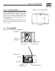
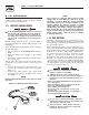
Section 3 — Operation Air-cooled 11 kW Generators 3.5 SETTING THE EXERCISE TIMER Figure 3.2 – Low Oil Pressure and High Temperature Switches This generator is equipped with an exercise timer. Once it is set, the generator will start and exercise once every seven days, on the day of the week and at the time of day the following sequence is completed. During this exercise period, the unit runs for approximately 12 minutes and then shuts down.
Section 4 — Maintenance Air-cooled 11 kW Generators 3.6.5 LOW BATTERY 4.2 The microprocessor will continually monitor the battery voltage and turn on the Low Battery LED if the battery voltage falls below 11.0 volts for one minute. Low battery voltage is a non-latching alarm, which will automatically clear if the battery voltage rises above 11.0 volts. For oil capacities, see “Specifications,” Section 1.5. For engine oil recommendations, see Section 4.3.1.
Section 4 — Maintenance Air-cooled 11 kW Generators 4.5 attempt to crank or start the engine before Any it has been properly serviced with the recommended oil may result in an engine failure. 4.3.2 OIL CHANGE PROCEDURE To change the oil, proceed as follows: 1. Run the engine until it is thoroughly warmed up then shut OFF the engine. 2. Immediately after the engine shuts OFF, pull the oil drain hose (Figure 4.3) free of its retaining clip.
Section 4 — Maintenance Air-cooled 11 kW Generators Figure 4.5 – Setting the Spark Plug Gap • Where electrolyte contacts the eyes, flush thoroughly and immediately with water and seek medical attention; and • Spilled electrolyte is to be washed down with an acid neutralizing agent. A common practice is to use a solution of 1 pound (500 grams) bicarbonate of soda to 1 gallon (4 liters) of water. The bicarbonate of soda solution is to be added until the evidence of reaction (foaming) has ceased.
Section 4 — Maintenance Air-cooled 11 kW Generators • Loosen the rocker jam nut. Use an 10mm allen wrench to turn the pivot ball stud while checking clearance between the rocker arm and the valve stem with a feeler gauge. Correct clearance is 0.002-0.004 inch (0.05-0.1 mm). NOTE: Figure 4.7 – Cooling Vent Locations Overhead View AIR OUTLET Hold the rocker arm jam nut in place as the pivot ball stud is turned.
Section 4 — Maintenance Air-cooled 11 kW Generators 7. Remove the spark plug(s) and spray fogging agent into the spark plug(s) threaded openings. Reinstall and tighten the spark plug(s). 8. Remove the battery and store it in a cool, dry room on a wooden board. Never store the battery on any concrete or earthen floor. 9. Clean and wipe the entire generator. 4.12.2 RETURN TO SERVICE To return the unit to service after storage, proceed as follows: 1.
Section 4 — Maintenance Air-cooled 11 kW Generators 4.13 SERVICE SCHEDULE ATTENTION: It is recommended that all service work be performed by the nearest Authorized Dealer. SYSTEM/COMPONENT X = Action R = Replace as Necessary * = Notify Dealer if Repair is Needed.
Section 5 — Troubleshooting Air-cooled 11 kW Generators 5.1 TROUBLESHOOTING GUIDE Problem Cause Correction The engine will not crank. 1. Fuse blown. 1. Replace 15A fuse in generator control panel. 2. Tighten, clean or replace as necessary. 3. * 4. Charge or replace battery. 2. Loose, corroded or defective battery cables. 3. Defective starter motor. 4. Dead Battery. The engine cranks but will not start. The engine starts hard and runs rough.
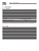
826 [32.54"] TOP VIEW **ALL DIMENSIONS IN: MILLIMETERS [INCHES] FRONT VIEW 1219 [48.00"] "DO NOT LIFT BY THE ROOF" (WITH ROOF OPEN) 1797 [70.76"] 76.2 [3.00"] PEA GRAVEL MINUMUM 790 [31.09"] RIGHT SIDE VIEW (SERVICE DOOR OPEN) 914 [36.00"] SWING ARC OF SERVICE DOOR 1219 [47.98"] AIR OUTLET 468 [18.43"] 457 [18.
Section 7 — Electrical Data Air-cooled 11 kW Generators Wiring Diagram – Drawing No.
Section 7 — Electrical Data Air-cooled 11 kW Generators Wiring Diagram – Drawing No.
Section 7 — Electrical Data Air-cooled 11 kW Generators Electrical Schematic – Drawing No.
Section 7 — Electrical Data Air-cooled 11 kW Generators Electrical Schematic – Drawing No.
Section 8 — Exploded Views and Parts Lists Air-cooled 11 kW Generators Enclosure – Drawing No.
Section 8 — Exploded Views and Parts Lists Air-cooled 11 kW Generators Enclosure – Drawing No. 0E4884-B ITEM PART NO. QTY.
Section 8 — Exploded Views and Parts Lists Air-cooled 11 kW Generators Control Panel – Drawing No.
Section 8 — Exploded Views and Parts Lists Air-cooled 11 kW Generators Control Panel – Drawing No. 0E4879-D ITEM PART NO. QTY.
Section 8 — Exploded Views and Parts Lists Air-cooled 11 kW Generators GT-990 Engine – Drawing No.
Section 8 — Exploded Views and Parts Lists Air-cooled 11 kW Generators GT-990 Engine – Drawing No. 0F2000 ITEM 1 2 3 4 5 6 7 8 9 10 11 12 13 14 15 16 17 18 19 20 21 22 23 24 25 26 27 28 29 30 31 32 33 34 35 36 37 38 39 40 41 42 43 44 45 46 47 48 49 50 51 52 53 54 55 56 PART NO.
Section 8 — Exploded Views and Parts Lists Air-cooled 11 kW Generators Engine Accessories – Drawing No.
Section 8 — Exploded Views and Parts Lists Air-cooled 11 kW Generators Engine Accessories – Drawing No. 0F2001-D ITEM PART NO. QTY.
Section 8 — Exploded Views and Parts Lists 46 26 30 24 9 1 34 41 42 28 31 32 22 23 10 21 11 27 17 16 4 4 2 3 3 6 15 14 3 18 19 20 33 8 34 12 5 51 5 38 4 44 43 40 39 38 47 48 50 49 53 25 38 37 36 3 35 Air-cooled 11 kW Generators Alternator & Pulleys – Drawing No.
Section 8 — Exploded Views and Parts Lists Air-cooled 11 kW Generators Alternator & Pulleys – Drawing No. 0E4880 ITEM 1 2 3 4 5 6 7 8 9 10 11 12 13 14 15 16 17 18 19 20 21 22 23 24 25 26 27 28 29 30 31 32 33 34 35 36 37 38 39 40 41 42 43 44 45 46 47 48 49 50 51 52 53 PART NO. QTY.
Section 8 — Exploded Views and Parts Lists 13 17 11 19 20 9 21 25 24 28 23 10 22 29 9 26 15 30 14 3 27 4 2 5 16 12 18 8 17 1 26 15 14 13 16 19 22 23 12 18 24 25 21 20 Air-cooled 11 kW Generators Regulator – Drawing No.
Section 8 — Exploded Views and Parts Lists Air-cooled 11 kW Generators Regulator – Drawing No. 0E4881-C ITEM 1 2 3 4 5 8 9 10 11 12 13 14 15 16 17 18 19 20 21 22 23 24 25 26 27 28 29 30 PART NO. 0D5694 0F5022 0C4647 0C4680 0C6070 0F4795 0D3973 0E6183 0E6184 0D3308 0C5761 0C5968 0C6066 0C5759 0C5764 070728 0C6069 0C5762 045764 0C6731 0C6067 0C4706 0C6068 0C4643A 026073 0E1010A 0C5760G 0C6606 QTY.
Section 9 — Notes Air-cooled 11 kW Generators 38
Section 9 — Notes Air-cooled 11 kW Generators 39
Section 10 – Warranty Air-cooled 11 kW Generators NOTE: This Emission Control Warranty Statement pertains to this product only IF the generator size is 15 kW or below. CALIFORNIA EMISSION CONTROL WARRANTY STATEMENT YOUR WARRANTY RIGHTS AND OBLIGATIONS The California Air Resources Board (CARB) and Generac Power Systems, Inc. (Generac) are pleased to explain the Emission Control System Warranty on your new engine.
Section 10 – Warranty Air-cooled 11 kW Generators EMISSION CONTROL SYSTEM WARRANTY Emission Control System Warranty (ECS Warranty) for 1995 and later model year engines: (a) Applicability: This warranty shall apply to 1995 and later model year engines. The ECS Warranty Period shall begin on the date the new engine or equipment is purchased by/delivered to its original, end-use purchaser/owner and shall continue for 24 consecutive months thereafter.
Section 10 – Warranty Air-cooled 11 kW Generators GENERAC POWER SYSTEMS “TWO YEAR” LIMITED WARRANTY FOR QUIETSOURCE™ “PREPACKAGED EMERGENCY AUTOMATIC STANDBY GENERATORS” For a period of two years from the date of original sale, Generac Power Systems, Inc. (Generac) warrants that its Quietsource generator will be free from defects in material and workmanship for the items and period set forth below.