Owner’s Manual and Installation Instructions Air-cooled Recreational Vehicle Generators • Model: 004701-0 QUIETPACT 40LP This manual should remain with the unit.
INTRODUCTION Thank you for purchasing this model by Generac Power Systems Inc. It has been designed and manufactured to supply electrical power for recreational vehicles. READ THIS MANUAL THOROUGHLY If any portion of this manual is not understood, contact the nearest Authorized Service Dealer for starting, operating and servicing procedures.
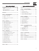
Table of Contents Recreational Vehicle Generator Part I – Owner’s Manual Part II – Installation Instructions Introduction ........................................Inside Front Cover Safety Rules ..................................................................... 18 Read This Manual Thoroughly ................................. IFC Contents .................................................................. IFC Operation and Maintenance ..................................... IFC How to Obtain Service ....
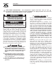
Safety Rules Recreational Vehicle Generator SAVE THESE INSTRUCTIONS – The manufacturer suggests that these rules for safe operation be copied and posted near the unit’s installation site. Safety should be stressed to all operators and potential operators of this equipment. WARNING: The engine exhaust from this product contains chemicals known to the state of California to cause cancer, birth defects or other reproductive harm.
Safety Rules Recreational Vehicle Generator • Adequate, unobstructed flow of cooling and ventilating air is critical to correct generator operation and is required to expel toxic fumes and fuel vapors from the generator compartment. Without sufficient cooling airflow, the engine/generator quickly overheats, which causes serious damage to the generator. Do not alter the installation or permit even partial blockage of ventilation provisions, as this can seriously affect safe operation of the generator.
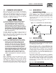
Section 1 – General Information Recreational Vehicle Generator 1.1 GENERATOR IDENTIFICATION Please record the following information from the generator DATA LABEL or information decal. 1. 2. 3. 4. 5. 6. 7. 8. 9. 1. Model Number _____________________ 2. Serial Number __________________ 3. kW Rating _________________________ 4.
Section 1 – General Information Recreational Vehicle Generator 1.2 GENERATOR APPLICABILITY These generators have been designed and manufactured for supplying electrical power for recreational vehicles. Do not modify the generator or use it for any application other than for what it was designed. If there are any questions pertaining to its application, write or call the factory. Do not use the unit until advised by a competent authority.
Section 2 – Operation Recreational Vehicle Generator 1.5.3 ENGINE OIL REQUIREMENTS 1.5.6 EMISSIONS COMPLIANCE PERIOD Use only high quality detergent oil rated with American Petroleum Institute (API) Service Classification SF, SG or SH. The recommended oil weights include the following: For non-handheld engines the Emissions Compliance Period referred to on the Emissions Compliance Label indicates the number of operating hours for which the engine has been shown to meet Federal emission requirements.
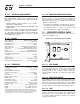
Section 2 – Operation Recreational Vehicle Generator 2.1.4 MAIN BREAKER 2.3.4 COOLING AND VENTILATING AIR The main breaker protects the generator’s AC output circuit against overload and provides a method of turning OFF the generator’s 120-volt AC output to the vehicle circuits. This generator has a 30-amp breaker. Air inlet and outlet openings in the generator compartment must be open and unobstructed for continued proper operation.
Section 2 – Operation Recreational Vehicle Generator To start the generator from either the generator control panel or from the optional remote panel, proceed as follows: 1. Turn OFF electrical loads using the means provided in the vehicle (such as a main line circuit breaker or transfer switch). NOTE: If starting from the generator control panel, turn OFF loads by setting the generator’s main circuit breaker to the OFF (or open) position.
Section 2 – Operation Recreational Vehicle Generator 2.8.2 HIGH TEMPERATURE SWITCH 2.8.4 OVERVOLTAGE PROTECTION This switch (Figure 2.2), which has normally open (N.O.) contacts, is mounted near the oil filter. The contacts close if the temperature should exceed approximately 284º F (140º C), initiating an engine shutdown. A solid-state voltage regulator (Figure 2.4) controls the generator’s AC output voltage. This regulator supplies an excitation current to the rotor.
Section 3 – Maintenance Recreational Vehicle Generator 2.9.2 25-HOUR CHECK-UP 2.9.5 EFFECTS OF MOISTURE AND DIRT After the 25-hour break-in period, contact an Authorized Service Dealer for the following maintenance. The vehicle owner is responsible for any charges: Keep the generator set as clean and dry as possible. Protect the unit against excessive dust, dirt, corrosive vapors, road splash, etc.
Section 3 – Maintenance Recreational Vehicle Generator 4. If necessary, remove the oil fill cap on the rocker cover and slowly add oil until it reaches the dipstick “Full” mark. DO NOT FILL ABOVE THE “FULL” MARK. operate the engine with the oil level Never below the “Add” mark on the dipstick. Doing 9. Install and tighten the oil fill cap and the dipstick before operating the engine. 10. Start the engine and check for leaks.
Section 3 – Maintenance Recreational Vehicle Generator 3.3.2 CLEANING OR REPLACING THE PAPER FILTER Once each year or every 100 hours of operation (whichever comes first), clean or replace the paper filter. The new replacement filter must be flame retardant. Service the paper filter more frequently if operating the generator in extremely dusty or dirty conditions. Use the following procedure (Figure 3.2): 1. Follow steps 1-3 in "Cleaning the Foam Precleaner"; service the foam precleaner if necessary. 2.
Section 3 – Maintenance Recreational Vehicle Generator Figure 3.5 - Spark Arrestor 3.8.2 EVERY SIX MONTHS • Have the state of charge and condition checked. This should be done with an automotive-type battery hydrometer. NOTE: TAILPIPE P/N 0E0683 Servicing of the battery is to be performed or supervised by personnel knowledgeable of batteries and the required precautions. Keep unauthorized personnel away from batteries. SPARK ARRRESTOR SCREEN P/N 089680 RETAINING SCREW P/N 056892 3.
Section 3 – Maintenance Recreational Vehicle Generator • Where electrolyte contacts the eyes, flush thoroughly and immediately with water and seek medical attention; and • Spilled electrolyte is to be washed down with an acid neutralizing agent. A common practice is to use a solution of 1 pound (500 grams) bicarbonate of soda to 1 gallon (4 liters) or water. The bicarbonate of soda solution is to be added until the evidence of reaction (foaming) has ceased.
Section 3 – Maintenance Recreational Vehicle Generator 2. When valve clearance is correct, hold the pivot ball stud with the allen wrench and tighten the rocker arm jam nut with a crows foot. Tighten the jam nut to 65-85 inch-pounds torque. After tightening the jam nut, recheck valve clearance to make sure it did not change (Figure 3.7). Figure 3.7 — Tightening Jam Nut 3.13 RV GENERATOR SERVICE INTERVAL 50 Hours ................................ Clean Spark Arrestor 100 Hours ...........................
Section 4 – Notes Recreational Vehicle Generator 16
PART II – INSTALLATION INSTRUCTIONS DANGER ONLY QUALIFIED ELECTRICIANS OR CONTRACTORS SHOULD ATTEMPT INSTALLATION!!
Safety Rules Recreational Vehicle Generator DANGER: For fire safety, installation of a generator into a recreational vehicle must comply strictly with article 551, NFPA 70; ANSI C1-1975; AND, ANSI A119.2-1975/NFPA 501C “Standard for Recreational Vehicles” (Part 3, “Installation of Electrical Systems”). In addition, installation must comply with the manufacturer’s instructions and recommendations.
Safety Rules Recreational Vehicle Generator ELECTRICAL HAZARDS FIRE HAZARDS • The generator covered by this manual produces dangerous electrical voltages and can cause fatal electrical shock. Avoid contact with bare wires, terminals, connections, etc., while the unit is running. Ensure all appropriate covers, guards and barriers are in place before operating the generator. If work must be done around an operating unit, stand on an insulated, dry surface to reduce shock hazard.
Section 1 – General Information Recreational Vehicle Generator 1.1 PURPOSE AND SCOPE OF THE MANUAL These Installation Instructions have been prepared especially for the purpose of familiarizing installers and owners of the applicable equipment with the product's installation requirements. Give serious consideration to all information and instructions in the manual, both for safety and for continued reliable operation of the equipment.
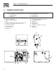
55.5 [2 3/16"] 376.5 [14 13/16"] 429.5 [16 15/16"] 476.4 [18 3/4"] 342.2 [13 1/2"] 29 [1 1/8"] 48.1 [1 7/8"] TAIL PIPE EXIT 416 [16 3/8"] HOT AIR EXHAUST TYP. 6.7 [1/4"] 50.8 [2"] 222.7 [8 3/4"] 210 [8 1/4"] 369.7 [14 9/16"] 343.4 [13 1/2"] 300.7 [11 13/16"] 101 [4"] 82.5 [3 1/4"] 423.2 [16 11/16"] 736.4 [29"] OIL DRAIN 36.5 [1 7/16 7/16"] 83.5 [3 5/16"] 176.6 [6 15/16"] 170 [6 11/16"] FRONT DOOR ACCESS FOR ALL REQUIRED MAINTENANCE 778.9 [30 11/16"] REF. 688.
Section 2 – Installation Recreational Vehicle Generator 2.1 LOCATION AND SUPPORT 2.1.1 GENERATOR LOCATION The most desirable location for the generator set is between the vehicle's main frame members. However, this is seldom possible. Most units must be installed on the side of the vehicle and are difficult to reinforce. Many recreational vehicles have been factory equipped with an area for the generator set. Some vehicles may even have a generator compartment provided by the vehicle manufacturer.
Section 2 – Installation Recreational Vehicle Generator 2.2 GENERATOR COMPARTMENTS Figure 2.4 – Typical Compartment Construction Whether the generator set is being installed inside a compartment specifically manufactured to house a generator or inside a compartment that the installer constructs, the compartment must meet certain specifications as outlined in the following sections: 2.2.1 COMPARTMENT SIZE Plan the compartment size carefully.
Section 2 – Installation Recreational Vehicle Generator Figure 2.5 – Types of Lock Seams NOTE: Any method used to reduce noise must not adversely affect the flow of cooling and ventilating air into or out of the compartment. In addition to the effective use of sound insulating materials, construction of a special noise abatement compartment might be considered to reduce noise levels. Such a compartment might be constructed as follows (Figure 2.
Section 2 – Installation Recreational Vehicle Generator Figure 2.
Section 2 – Installation Recreational Vehicle Generator DANGER Fuel lines and exhaust piping must not penetrate into the vehicle living area. 2.3 COOLING AND VENTILATING AIR It is absolutely essential that an adequate flow of air for cooling, ventilating and engine combustion be supplied to the generator set. Without sufficient airflow, the engine/generator quickly overheats. Such overheating can cause serious operating difficulties and also may cause fire and personal injury.
Section 2 – Installation Recreational Vehicle Generator Figure 2.9 – Typical Propane Gas Fuel System 2.4.4 PRIMARY REGULATOR Gas pressure delivered to the solenoid valve must be properly regulated by means of a primary gas regulator. Mount the primary regulator at the gas tank outlet or in the supply line from the gas tank. The following rules apply: • For best results, the primary regulator supplies gaseous fuel to the secondary regulator at 11 inches water column. Do NOT exceed 14 inches water column.
Section 2 – Installation Recreational Vehicle Generator The greater the airflow through the carburetor venturi, the lower the pressure at the venturi throat. The lower the pressure at the venturi throat, the greater the diaphragm movement, and the greater the movement of the regulator valve. The more the regulator valve opens, the greater the gas flow that is proportional to airflow through the generator.
Section 2 – Installation Recreational Vehicle Generator 2.5.1 SPARK ARRESTOR 2.5.2 EXHAUST SYSTEM SAFETY This spark arrestor assembly meets code and standard requirements of the U.S. Forest Service. Use only mufflers and parts approved by the manufacturer.
Section 2 – Installation Recreational Vehicle Generator • Wiring must be of adequate size, have approved insulative qualities and be properly supported. • Conduit and wire openings into the generator compartment (if used) must be vapor-sealed to prevent entry of flammable, explosive or poisonous gases into the vehicle. Figure 2.13 – Generator AC Output Leads REMOTE PANEL CONNECTOR 500.2 [19 11/16"] REF. AC OUTPUT HARNESS 2.6.
Section 2 – Installation Recreational Vehicle Generator Figure 2.14 – Transfer Switch Isolation Method Figure 2.
Section 2 – Installation Recreational Vehicle Generator 2.6.6 POWER SUPPLY CORD 2.7.3 BATTERY CABLE CONNECTIONS The power supply cord must comply with all applicable codes, standards and regulations. It must be large enough to handle the full amperage to which it will be subjected. 1. Connect the battery cable from the battery post or terminal indicated by a POSITIVE, POS or (+) to the lug on the starter contactor (Figure 2.16).
Section 3 – Post-installation Start-up Adjustments Recreational Vehicle Generator Figure 2.17 – Remote Panel Plug-in Receptacle 3.1 POST INSTALLATION TESTS The air-cooled generator set was factory tested and adjusted. It should not be required to adjust the unit any further except under special circumstances. not make any unnecessary adjustments. Do Factory settings are correct for most applica14A 6 4 15 18 18 17 17 14 3 2 14 0 1 tions.
Section 3 – Post-installation Start-up Adjustments Recreational Vehicle Generator 6. Turn off all electrical loads by setting the generator’s main circuit breakers to their “OFF” (or open) position. 7. Let the unit run at no-load for a few minutes to stabilize internal engine/generator temperatures. Then, shut down the engine. NOTE: The generator set was thoroughly tested and adjusted at the factory before shipping. No additional adjustment should be necessary.
Section 3 – Post-installation Start-up Adjustments Recreational Vehicle Generator 3.5 INSTALLATION CHECKLIST ELECTRICAL CONNECTIONS LOCATION AND SUPPORT ❑ Connections comply with local code requirements and all National Electrical Codes. ❑ Generator is properly located. ❑ Junction box is properly installed. ❑ Generator is properly supported. ❑ Generator is properly restrained. GENERATOR COMPARTMENT ❑ Compartment construction is proper. ❑ Wiring meets all standards.
Section 4 – Troubleshooting Recreational Vehicle Generator TROUBLESHOOTING GUIDE Problem Cause Correction The engine will not crank. 1. Fuse blown 2. Loose, corroded or defective battery cables 3. Defective engine Start/Stop switch 4. Defective starter contactor 5. Defective starter motor 6. Low or defective battery 1. Replace fuse. 2. Tighten, clean or replace as necessary. 3. Replace Start/Stop switch. The engine cranks but will not start. 1. Out of fuel 2. Defective fuel solenoid 3.
Section 5 – Notes Recreational Vehicle Generator 37
Section 6 — Electrical Data Recreational Vehicle Generator Electrical Schematic and Wiring Diagram – Drawing No.
Section 6 — Electrical Data Recreational Vehicle Generator Electrical Schematic and Wiring Diagram – Drawing No.
Section 7 — Exploded Views and Parts Lists Recreational Vehicle Generator Enclosure – Drawing No.
Section 7 — Exploded Views and Parts Lists Recreational Vehicle Generator Enclosure – Drawing No. 0F4589-B ITEM 1 2 3 4 5 6 7 8 9 10 11 12 13 14 15 16 17 18 19 20 21 22 23 24 25 26 27 28 30 31 32 33 34 35 36 37 38 39 40 41 42 43 44 45 46 47 48 49 50 51 52 53 54 55 56 PART NO.
Section 7 — Exploded Views and Parts Lists Recreational Vehicle Generator Generator – Drawing No.
Section 7 — Exploded Views and Parts Lists Recreational Vehicle Generator Generator – Drawing No. 0F4590-C ITEM 1 2 3 4 5 6 7 8 9 10 11 12 13 14 15 16 17 18 19 20 21 22 23 24 25 26 27 28 29 30 31 32 33 34 35 36 37 38 39 41 42 43 PART NO.
Section 7 — Exploded Views and Parts Lists Recreational Vehicle Generator Control Panel – Drawing No.
Section 7 — Exploded Views and Parts Lists Recreational Vehicle Generator Control Panel – Drawing No. 0F4591-A ITEM 1 2 3 4 5 6 7 8 9 10 11 12 13 14 15 16 17 18 19 20 21 22 23 24 25 26 27 28 29 30 31 32 33 34 35 36 37 PART NO. 0F9719 075210A 092234 065795 023484F 023484R 075234 057159 054502 087798 092113 032300 0A9611 090145 0E2314 0A1658 075235 047411 049226 051716 075476 022264 051715 0A2053 022473 022097 049813 055440 049815 038750 051714 0D8794 025105 028739 0D8308 0F5025 023484S 043182 031879 QTY.
Section 7 — Exploded Views and Parts Lists Recreational Vehicle Generator GN-220 H/SH Engine – Drawing No.
Section 7 — Exploded Views and Parts Lists Recreational Vehicle Generator GN-220 H/SH Engine – Drawing No. 0F5791-G Part 1 ITEM PART NO. QTY.
Section 7 — Exploded Views and Parts Lists Recreational Vehicle Generator GN-220 H/SH Engine – Drawing No.
Section 7 — Exploded Views and Parts Lists Recreational Vehicle Generator GN-220 H/SH Engine – Drawing No. 0F5791-G Part 2 ITEM PART NO.
Section 7 — Exploded Views and Parts Lists Recreational Vehicle Generator Regulator – Drawing No.
Section 7 — Exploded Views and Parts Lists Recreational Vehicle Generator Regulator – Drawing No. 0F5819 ITEM 1 2 3 4 5 6 7 8 9 10 11 12 13 14 15 16 17 18 19 20 21 22 23 24 25 26 PART NO. 0D5694 0F4795 0F5022 0C6070 0C4680 0C4647 0C4643 0D3973 0D7020A 026073 0D3308 070728 0C5764 0C4643A 0C5764 0C5968 0C5759 0C5761 0C6069 0C6731 0C6067 0C4706 0C6068 0C5762 045764 0C5760K QTY. 1 4 1 1 1 1 1 1 1 2 2 2 1 1 1 1 1 1 1 1 1 1 1 1 8 1 DESCRIPTION CASTING, TWIN REGULATOR HOUSING SCREW PPHM SEMS M4-0.
Section 8 – Warranty Recreational Vehicle Generator CALIFORNIA AND FEDERAL EMISSION CONTROL WARRANTY STATEMENT YOUR WARRANTY RIGHTS AND OBLIGATIONS The California Air Resources Board (CARB) and the United States Environmental Protection Agency (EPA), together with Generac Power Systems, Inc. (Generac), are pleased to explain the Emission Control System Warranty on your new engine.
Section 8 – Warranty Recreational Vehicle Generator EMISSION CONTROL SYSTEM WARRANTY Emission Control System Warranty (ECS Warranty) for 1997 and later model year engines: (a) Applicability: This warranty shall apply to 1997 and later model year engines. The ECS Warranty Period shall begin on the date the new engine or equipment is purchased by/delivered to its original, end-use purchaser/owner and shall continue for 24 consecutive months thereafter.
Section 8 – Warranty Recreational Vehicle Generator GENERAC POWER SYSTEMS’ THREE-YEAR LIMITED WARRANTY FOR GUARDIAN RECREATIONAL VEHICLE GENERATORS NOTE: ALL UNITS MUST BE INSTALLED BY GENERAC POWER SYSTEMS AUTHORIZED SERVICE FACILITIES. For a period of 3 (three) years of operation from the date of original sale, Generac Power Systems, Inc.