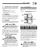
Automatic Transfer Switch Owner’s Manual ATS “HS” Type Models: 004635-3 (200 Amp, 250 Volts) and 004678-2 (100 Amp, 250 Volts) This manual should remain with the unit.
IMPORTANT SAFETY INSTRUCTIONS ! ! SAVE THESE INSTRUCTIONS! Read the following information carefully before attempting to install, operate or service this equipment. Also read the instructions and information on tags, decals, and labels that may be affixed to the transfer switch. Replace any decal or label that is no longer legible.
Table of Contents • Remove all jewelry (such as rings, watches, bracelets, etc.) before working on this equipment. • If work must be done on this equipment while standing on metal or concrete, place insulative mats over a dry wood platform. Work on this equipment only while standing on such insulative mats. • Never work on this equipment while physically or mentally fatigued. • Keep the transfer switch enclosure door closed and bolted at all times.
Section 1 — General Information ATS “HS” Type Transfer Switch 1.1 INTRODUCTION This manual has been prepared especially for the purpose of familiarizing personnel with the design, application, installation, operation and servicing of the applicable equipment. Read the manual carefully and comply with all instructions. This will help to prevent accidents or damage to equipment that might otherwise be caused by carelessness, incorrect application, or improper procedures.
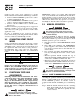
Section 2 — Installation GTS “HS” Type Transfer Switch 2.1 INTRODUCTION TO INSTALLATION This equipment has been wired and tested at the factory. Installing the switch includes the following procedures: • • • • • Mounting the enclosure. Connecting power source and load leads. Connecting the generator start circuit. Connecting any auxiliary contact (if needed) Testing functions. 2.2 2.4.1 2-POLE MECHANISM These switches (Figure 2.
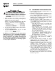
Section 3 — Operation ATS “HS” Type Transfer Switch Connect power source load conductors to clearly marked transfer mechanism terminal lugs as follows 1. Connect UTILITY (NORMAL) power source cables to switch terminals N1, N2. 2. Connect EMERGENCY (STANDBY) source power cables to transfer switch terminals E1, E2. 3. Connect customer LOAD leads to switch terminals T1, T2.
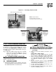
Section 3 — Operation ATS “HS” Type Transfer Switch Figure 3.1 — Actuating Transfer Switch Attach handle to actuating shaft. NOTE: Return handle to storage position in enclosure when finished with manual transfer. Move handle UP for the NORMAL (UTILITY) position. Move handle DOWN for the EMERGENCY (STANDBY) position. ◆ 3.2.2 CLOSE TO EMERGENCY SOURCE SIDE DANGER Before proceeding, verify the position of the switch by observing the position of the manual operation handle in Figure 3.1.
Section 3 — Operation ATS “HS” Type Transfer Switch DANGER PROCEED WITH CAUTION. GENERATOR OUTPUT VOLTAGE IS NOW BEING DELIVERED TO TRANSFER SWITCH TERMINALS. CONTACT WITH LIVE TERMINALS RESULTS IN EXTREMELY DANGEROUS AND POSSIBLY FATAL ELECTRICAL SHOCK. 7. With an accurate AC voltmeter and frequency meter, check the no-load, voltage and frequency. Single-phase generator supply: Measure across ATS terminal lugs E1 to E2. Also check E1 to NEUTRAL and E2 to NEUTRAL. a. b. c. d. Frequency ...................
Section 4 — Notes ATS “HS” Type Transfer Switch 7
Section 4 — Notes ATS “HS” Type Transfer Switch 8
Section 4 — Notes ATS “HS” Type Transfer Switch 9
10 KNOCKOUT SUITABLE FOR 1", 1-1/2" AND 2" CONDUIT SIZE 3 PLACES 179.5mm[7.07"] 508.5mm[20.02"] 377mm[14.84"] Ø6.3mm[Ø0.25"] 294mm[11.57"] 45mm[1.77"] 420mm[16.54"] 41.5mm[1.63"] Section 5 — Installation Diagram ATS “HS” Type Transfer Switch Drawing No.
TRANSFER SWITCH SWITCH TYPE, SPST ELECTRICAL RATINGS, 2A @ 250Vac MIN. - OPEN SWITCH TO TEST - REMOTE TEST SWITCH (OPTIONAL) UTILITY 1 UTILITY 2 LOAD 1 LOAD 2 NEUTRAL LUG POWER LEADS AND TRANSFER SWITCH LEADS MUST BE RUN IN TWO DIFFERENT CONDUITS. NOTE: NOTE: IF THERE ARE NO MATCHING TERMINAL CONNECTIONS FOR LOAD 1 (T1) AND LOAD 2 (T2) IN THE GENERATOR CONTROL PANEL DO NOT CONNECT THESE WIRES, FAILURE OF THE CONTROL BOARD WILL OCCUR IF CONNECTED.
Section 6 — Electrical Data ATS “HS” Type Transfer Switch Electrical Schematic - Drawing No.
Section 6 — Electrical Data ATS “HS” Type Transfer Switch Electrical Schematic - Drawing No.
8 9 6 14 GENERAC POWER SYSTEMS, INC. WAUKESHA, WI. OR ALUMINUM WIRE OF AT LEAST 75° C RATING 120/240 (GROUND LUG ASSEMBLY) SWITCH RATING ENCLOSURE 0A9517 7 3 15 23 26 19 40 22 ***** **** 10 (POWER TERMINAL LUG ASSEMBLY) NOTE: TORQUE ITEM #3 TO 24-30 IN.
Section 7 — Exploded Views and Parts List ATS “HS” Type Transfer Switch 100A Transfer Switch Assembly – Drawing No. 0E8403$-F ITEM PART NO.
8 9 120/240 6 SERIAL NUMBER WS3 4X1 4S DETAIL A-A 0A9517 22097 S (GROUND LUG ASSEMBLY) SYSTEM VOLTAGE 057329-S ENCLOSURE 15 22 31 19 28 7 *** 20 ***** **** 10 21 16 13 11 13 ***** 14 CS3-8X16T 8X16 C CS 29 27 C PT/NO A25955 23 26 A 40 UTILITY 2 LOAD 1 16 23 41 A 194 18 ***** 63378 T 63378-T A 42 A A 30 NEUT A A 5 C 8X16 CS3-8X16T 33 25 3 4 24 17 12 34 38 1 35 3 TO 72±1 IN-LBS 36 NOTE: TORQUE ITEM 2 ** Section 7 — Exploded Views and P
Section 7 — Exploded Views and Parts List ATS “HS” Type Transfer Switch 200A Transfer Switch Assembly – Drawing No. 0E5782$-J ITEM PART NO.
Section 8 — Warranty ATS “HS” Type Transfer Switch GENERAC POWER SYSTEMS, INC. WARRANTY/SERVICE Generac Power Systems, Inc. will warrant from the date of purchase that our transfer switch will be free from defects in material and workmanship for the items and periods set forth in the warranty statement found in the owners manual of the Generac Power Systems Inc. generator that this transfer switch will be utilized with.