Owner’s Manual Liquid-cooled, Prepackaged Standby Generators Models: 004373-6 (40 kW/Single-phase w/ 200 Amp Transfer Switch) 004626-5 ® POWER SYSTEMS, INC. ® (40 kW/Single-phase w/ 200 Amp Transfer Switch California Emissions) ! Not intended for use in critical life support applications. ! ONLY QUALIFIED ELECTRICIANS OR CONTRACTORS SHOULD ATTEMPT INSTALLATION!! DEADLY EXHAUST FUMES. OUTDOOR INSTALLATION ONLY! This manual should remain with the unit.
INTRODUCTION Thank you for purchasing the Guardian product line by Generac Power Systems. This model is a compact, high performance, liquid-cooled, engine-driven generator designed to automatically supply electrical power to operate critical loads during a utility power failure. This unit is factory installed in an all-weather, metal enclosure that is intended exclusively for outdoor installation. READ THIS MANUAL THOROUGHLY The operator is responsible for proper and safe use of the equipment.
Table of Contents Guardian Liquid-cooled 40 kW Generator Introduction ........................Inside Front Cover Section 3 – Operation ....................................12 Read This Manual Thoroughly ............................IFC Contents ..............................................................IFC Operation and Maintenance ................................IFC How to Obtain Service ........................................IFC Authorized Dealer Locator Number ........................IFC 3.
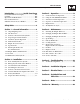
IMPORTANT SAFETY INSTRUCTIONS Guardian Liquid-cooled 40 kW Generator ! SAVE THESE INSTRUCTIONS – The manufacturer suggests that these rules for safe operation be copied and posted in potential hazard areas. Safety should be stressed to all operators and potential operators of this equipment. ! ! SAVE THESE INSTRUCTIONS – This manual contains important instructions that should be followed during installation and maintenance of the generator and batteries.
Important Safety Instructions Guardian Liquid-cooled 40 kW Generator • Inspect the generator regularly, and promptly repair or replace all worn, damaged or defective parts using only factory-approved parts. • Before performing any maintenance on the generator, disconnect its battery cables to prevent accidental start-up. Disconnect the cable from the battery post indicated by a NEGATIVE, NEG or (–) first. Reconnect that cable last. • Never use the generator or any of its parts as a step.
Section 1 — General Information Guardian Liquid-cooled 40 kW Generator 1.1 UNPACKING/INSPECTION After unpacking, carefully inspect the contents for damage. • This standby generator set has been factory installed in an all-weather, metal enclosure that is intended exclusively for outdoor installation. If this generator is used to power electrical load circuits normally powered by a utility power source, code requires to install a transfer switch.
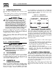
Section 1 — General Information Guardian Liquid-cooled 40 kW Generator 1.6 MAIN CIRCUIT BREAKER The generator’s main circuit breaker is included with the unit as shipped from the factory. The breaker for each unit is described as follows: 1.
Section 1 — General Information Guardian Liquid-cooled 40 kW Generator 1.8.2 GENERATOR AND LOAD COMPATIBILITY The generator must be fully compatible with the rated voltage, number of phases and frequency of the connected electrical loads. The generator, connected electrical devices, or both, can be damaged if voltage, number of phases and frequency are not compatible.
Section 1 — General Information Guardian Liquid-cooled 40 kW Generator 1.10 ENGINE OIL RECOMMENDATIONS The unit has been filled with 15W-40 engine oil at the factory. Use a high-quality detergent oil classified “For Service CC, SD, SE or SF.” Detergent oils keep the engine cleaner and reduce carbon deposits.
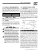
Section 2 — Installation Guardian Liquid-cooled 40 kW Generator STANDBY GENERATOR INSTALLATION DANGER Connecting this generator to an electrical system normally supplied by an electric utility shall be by means of a transfer switch (such as the Generac “Pre-packaged” type transfer switch), so as to isolate the electric system from the utility distribution system when the generator is operating.
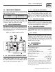
Section 2 — Installation Guardian Liquid-cooled 40 kW Generator Figure 2.1 – Basic Standby Electric System DANGER Do not connect the ground wire to any pipe that carries a flammable or explosive substance – FIRE or an EXPLOSION may result. Proper grounding helps protect personnel against electrical shock in the event of a ground fault condition in the generator or in connected electrical devices. In addition, grounding helps dissipate static electricity that often builds up in ungrounded devices.
Section 2 — Installation Guardian Liquid-cooled 40 kW Generator 2.7 BATTERY INSTALLATION 2.7.1 VENTED BATTERIES DANGER ! Standby generators installed with automatic transfer switches will crank and start automatically when NORMAL (UTILITY) source voltage is removed or is below an acceptable preset level.
Section 2 — Installation Guardian Liquid-cooled 40 kW Generator 2.8 PREPARATION BEFORE START-UP The instructions in this section assume that the standby generator has been properly installed, serviced, tested, adjusted and otherwise prepared for use by a competent, qualified installation contractor. Be sure to read the “Safety Rules” on Pages 2 and 3, as well as all other safety information in this manual, before attempting to operate this (and related) equipment. 2.8.
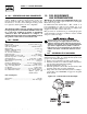
Section 3 — Operation Guardian Liquid-cooled 40 kW Generator 3.1 CONTROL CONSOLE COMPONENTS The components of a liquid-cooled generator control console (Figure 3.1) are as follows: Figure 3.1 – Control Console 3.1.5 HOURMETER This indicates the time the engine-generator has operated, in hours and tenths of hours. Use the hourmeter along with the periodic maintenance schedule for the generator set. 3.1.6 AUTO/OFF/MANUAL SWITCH See Section 3.2. 3.1.
Section 3 — Operation Guardian Liquid-cooled 40 kW Generator 3.2.2 “OFF” POSITION This switch position shuts down the engine. This position also prevents operation. 3.2.3 “MANUAL” POSITION Set the switch to MANUAL to crank and start the engine. Transfer to standby power will not automatically occur unless there is a utility failure. ! 3.3 With the switch set to AUTO, the engine may crank and start at any time without warning.
Section 4 — Maintenance Guardian Liquid-cooled 40 kW Generator NOTE: Figure 3.2 – Engine Block Heater OUTLET If the battery terminals are disconnected or the control panel fuse is removed, the exercise timer needs to be reset for automatic exercise operation. Figure 3.3 – “Set Exercise” Switch on Control Panel INLET Refer to applicable wiring diagram(s) and electrical schematic(s) at the back of this manual for wiring connections. 3.
Section 4 — Maintenance Guardian Liquid-cooled 40 kW Generator 4.2 CHANGING THE ENGINE OIL AND FILTER 4.2.1 ENGINE OIL RECOMMENDATIONS Use oil of API Service Class SG, SH or SJ. The recommended oil grade for the engine is SAE 15W-40. 5. Apply a light coating of clean engine oil to the seal of new oil filter. Install the filter and tighten by hand only. DO NOT OVERTIGHTEN. 6. Remove the oil fill cap (Figure 4.1). Add the recommended oil (see Section 4.2.1). DO NOT FILL ABOVE THE DIPSTICK “FULL” MARK.
Section 4 — Maintenance Guardian Liquid-cooled 40 kW Generator 4.4 SPARK PLUGS Reset the spark plug gap or replace the spark plugs as necessary. See Section 4.12. 1. Clean the area around the base of the spark plugs to keep dirt and debris out of the engine. Clean the plugs by scraping using a wire brush. Do not “blast” the spark plugs to clean. 2. Remove the spark plugs and check the condition. Replace the spark plugs if worn or if reuse is questionable. See the “Service Schedule,” Section 4.
Section 4 — Maintenance Guardian Liquid-cooled 40 kW Generator 4.7 OVERLOAD PROTECTION FOR ENGINE DC ELECTRICAL SYSTEM Engine cranking, start-up and running are controlled by a solid-state engine controller circuit board. Battery voltage is delivered to that circuit board via a 15-amp fuse. These overcurrent protection devices will open if the circuit is overloaded.
Section 4 — Maintenance Guardian Liquid-cooled 40 kW Generator 4.11 OUT OF SERVICE PROCEDURE 4.11.2 RETURN TO SERVICE 4.11.1 REMOVAL FROM SERVICE To return the unit to service after storage, proceed as follows: If the generator cannot exercise every seven days, and it is to be out of service longer than 90 days, prepare the generator for storage as follows: 1. Verify that UTILITY power is turned off to the transfer switch and that the AUTO/OFF/MANUAL switch is set to OFF. 2.
Section 4 — Maintenance Guardian Liquid-cooled 40 kW Generator 4.12 SERVICE SCHEDULE ATTENTION: It is recommended that all service work be performed by the nearest Generac/Guardian Authorized Dealer. SYSTEM/COMPONENT X = Action R = Replace/Adjust as Needed * = Notify Dealer if Repair is Needed.
Section 5 — Troubleshooting Guardian Liquid-cooled 40 kW Generator 5.1 TROUBLESHOOTING GUIDE PROBLEM CAUSE CORRECTION The engine will not crank. 1. Fuse blown 2. Loose, corroded or defective battery cables 3. Defective starter contactor 4. Defective starter motor 5. Dead Battery 1. Replace fuse. 2. Tighten, clean or replace as necessary. 3. * 4. * 5. Charge or replace battery. The engine cranks but will not start. 1. Out of fuel 2. Defective fuel solenoid (FS) 3.
Section 6 — Installation Diagram Guardian Liquid-cooled 40 kW Generator Drawing No. 0E7015 Generac® Power Systems, Inc.
Section 7 — Electrical Data 219 150 86 85 69 68 56 229 4 15 15 15 14 14 13 79 0 0 0 (Model No. 0043733, 0043734 & 0043735) Guardian Liquid-cooled 40 kW Generator Electrical Schematic (Stepper Motor) – Drawing No. 0A5858 TS1 GCB BLACK RED P/N 98647 S16 BLUE HZ BLUE LEGEND GCB - GOVERNOR CONTROL BOARD HZ - FREQUENCY METER TB1 - TERMINAL BLOCKS 22 Generac® Power Systems, Inc.
12 EH 13 A LEGEND 14 14 13 10 14 85 85 0 56 85 85 GCU 0 56 AM - METER, AC OUTPUT CURRENT AVR - AUTOMATIC VOLTAGE REGULATOR BVM - METER, BATTERY VOLTAGE CAP - CAPACITOR CB1 - CIRCUIT BREAKER- EXCITATION CP - CONNECTION, LOWER PANEL D1 - DIODE- 600V, 12A EH - ENGINE HARNESS CONNECTION F1 - FUSE 15A F2 - FUSE 7.
TO ENGINE (CONNECTOR EH) TO LOWER PANEL (CONNECTOR CP) 29 1 4 13 14 14 0 4 162 1 0 85 56 14 S15 A T1 17 S15 T2 16 RED BLACK GCU BLUE BLUE 225A 176 RED N2 23 194 183 178 N2 23 194 183 178 W X B J BLACK T1 T2 BLUE T1 225A T TO GOVERNOR ACTUATOR CONTROLLER CONNECTOR BLUE BLUE 23 176 15A 15C 15A N1 O O O O O 0 194 15C 15A F2 SW2 N1 0 X 19 - 14 O O X O O X X 1 2 3 OFF F X X 3 15 E 4 12 POSITION HZ RED 14 9 15 - 14 15 - 18 12 - 3 12 -
6 NB 57 SCHEMATIC 120/240-V.
14 160 13 14 14 14 13 14 161 7 ACT- 161 BAT- 0 EH 6 5 4 85 85 0 56 MPU+ 85 79 85 MPU- 0 0 BAT+ 14 56 MPU SHIELD 0 N1 56 0 14 N2 AVR N1 N2 BLACK RED 13 85 N2 14 85 85 14 3 5 6 2 1 4 6 1 0 TS2 56 S16 S15 4 162 13 BLACK 4 162 TR1 GRD RED D1 BLACK 29 2 S16 13 0 162 13 4 15 17 16 T2 T1 T2 14 0 0 S15 0 0 0 1 14 14 4 14 0 0 13 4 14 4 56 56 56 4 4 85 85 BLUE 12 11 10 9 PCB T1 0 14 14 14 14 14 4 13 USE BLUE WIRE
TO ENGINE (CONNECTOR EH) TO LOWER PANEL (CONNECTOR CP) 4 0 4 S3 57 M N 162 0 S15 A T1 17 7 S15 T2 16 PCB 5 56 3 15 E 4 10 12 1 2 3 OFF F POSITION HZ RED 14 9 178 23 176 PFC 225A 15C BAT- BAT+ 176 0 14 T1 N1 N2 23 194 183 178 N1 N2 23 194 183 178 S T W X B J T1 T2 BLUE SW2 225A 15C T1 0 194 15C 15E 15A T2 0 15 - 18 19 - 16 19 - 14 X INDICATES CLOSED 12 - 7 12 - 11 2-3 2-7 2 - 11 CONTACTS VM 11 178 T2 67 AM + 0 64 65 D 229 239
Section 7 — Electrical Data Guardian Liquid-cooled 40 kW Generators Wiring Diagram - Drawing No.
Section 7 — Electrical Data Guardian Liquid-cooled 40 kW Generators Wiring Diagram - Drawing No.
Section 8 — Exploded Views and Parts Lists Guardian Liquid-cooled 40 kW Generators Mounting Base - Drawing No. 0E6976-A 28 27 BLACK 26 9 7 38 RED 2 18 4 37 12 19 11 10 39 36 38 TO STARTER SOLENOID 29 35 7 8 14 6 15 18 20 15 1 5 12 19 To Oil Drain On Oil Pan. 23 11 10 21 22 116 17 13 24 34 25 25 32 16 3 12 17 31 30 3 25 30 Generac® Power Systems, Inc.
Section 7 — Exploded Views and Parts Lists Guardian Liquid-cooled 40 kW Generators Mounting Base - Drawing No. 0E6976-A ITEM 1 2 3 4 5 6 7 8 9 10 11 12 13 14 15 16 17 18 19 20 21 22 23 24 25 26 27 28 29 30 31 32 33 34 35 36 37 38 39 PART NO.
Section 8 — Exploded Views and Parts Lists 17 6 29 30 22 36 31 25 26 3 1 24 23 29 32 Generac® Power Systems, Inc. 2 (ONE PER SIDE) 3 8 39 1 15 5 11 32 33 34 28 2 29 9 11 12 12 2 BASE FRAME 13 27 5 29 11 11 19 29 10 10 27 5 7 16 42 21 Guardian Liquid-cooled 40 kW Generators Compartment - Drawing No.
Section 8 — Exploded Views and Parts Lists Guardian Liquid-cooled 40 kW Generators Compartment - Drawing No. 0D8992-A ITEM PART NO. QTY.
34 Generac® Power Systems, Inc. 12 VIEW A-A 13 59 18 17 16 35 5 6 20 19 18 49 50 21 64 36 42 60 A A 9 37 60 61 61 41 51 52 53 58 39 3 51 52 53 58 43 23 29 26 28 24 25 27 45 46 47 48 18 49 50 62 63 - 15 52 53 1 + 14 54 55 56 57 4 18 49 50 3 22 30 31 32 2 EVERY 7 DAYS, AT TIME SET. SET 81988 IM E 33 V PANEL FACE A 3 0 Hz 1 INSIDE. 34 Section 8 — Exploded Views and Parts Lists (Model No.
Section 8 — Exploded Views and Parts Lists (Model No. 0043733, 0043734 & 0043735) Guardian Liquid-cooled 40 kW Generator Control Panel 4.3L – Drawing No. 0D4995-F ITEM PART NO. QTY.
Section 8 — Exploded Views and Parts Lists (Model No. 0046262, 0046263 & 0046264) Guardian Liquid-cooled 40 kW Generator Control Panel – Drawing No. 0D6978-C 36 Generac® Power Systems, Inc.
Section 8 — Exploded Views and Parts Lists (Model No. 0046262, 0046263 & 0046264) Guardian Liquid-cooled 40 kW Generator Control Panel – Drawing No. 0D6978-C ITEM PART NO. QTY.
Section 8 — Exploded Views and Parts Lists Guardian Liquid-cooled 40 kW Generators Connection Box – Drawing No. 0E6892-A 38 Generac® Power Systems, Inc.
Section 8 — Exploded Views and Parts Lists Guardian Liquid-cooled 40 kW Generators Connection Box – Drawing No. 0E6892-A ITEM 1 2 3 4 5 6 7 8 9 10 11 12 13 14 15 16 17 18 19 20 21 22 23 24 25 26 27 28 29 30 31 32 33 34 PART NO. 0E6353 0D5489 0E6427 023484N 0E6454 056739 0C2454 051715 0D3388 058710 0D5492 (048766) 022985 0E6689 022264 052813 039253 022145 0D5840 022129 045771 022287 022473 022097 022127 0E4458 0E5586 0E5587 022237 022241 081320 048527 0D5464B 057073 0C2266 QTY. 1 1 1 2 1 1 2 2 1 2 1 REF.
40 Generac® Power Systems, Inc. 6 9 35 18 19 32 15 16 17 11 21 10 12 22 13 14 DO NOT ROTATE ENGINE DURING THIS ADJUSTMENT. 28 29 23 40 24 41 40 38 25 39 36 2 21 34 33 36 SCROLL DETAIL 5 20 31 7 37 CAUTION: 19 5 3 43 1 18 35 4 2 TO ENGINE FLYWHEEL THREAD IN SENSOR (6) UNTIL CONTACT IS MADE WITH RING GEAR, THEN BACK OFF 1/2 TO 3/4 TURN AND TIGHTEN NUT.
Section 8 — Exploded Views and Parts Lists Guardian Liquid-cooled 40 kW Generators Generator – Drawing No. 0E6891 ITEM PART NO. QTY.
Section 8 — Exploded Views and Parts Lists Guardian Liquid-cooled 40 kW Generators Engine – Drawing No. 0D6980-D 42 Generac® Power Systems, Inc.
Section 8 — Exploded Views and Parts Lists Guardian Liquid-cooled 40 kW Generators Engine – Drawing No. 0D6980-D ITEM 1 2 3 4 6 8 9 10 11 12 13 14 15 16 17 18 19 20 21 22 23 24 25 26 27 28 29 30 31 32 33 34 35 36 37 38 39 40 41 42 43 44 * * PART NO.
Section 8 — Exploded Views and Parts Lists 35 26 34 19 34 20 22 39 40 43 32 44 Generac® Power Systems, Inc. 40 23 31 45 24 6 48 40 37 43 5 10 33 31 4 13 11 36 25 34 3 21 46 40 14 41 8 7 44 2 27 2 18 30 47 50 9 1 12 16 26 17 34 38 15 Guardian Liquid-cooled 40 kW Generators Engine – Drawing No.
Section 8 — Exploded Views and Parts Lists Guardian Liquid-cooled 40 kW Generators Engine – Drawing No. 0A4304-N ITEM PART NO. QTY.
Section 8 — Exploded Views and Parts Lists 10 16 11 1 14 27 12 40 29 16 36 18 33 34 35 31 30 KIT PART NO. 0D7948 19 20 32 KIT PART NO. 0D7947 37 38 39 46 Generac® Power Systems, Inc. KIT PART NO. 0D8121 9 6 "A" 10 15 27 5 22 7 22 24 23 2 17 17 TO "A" 10 21 Guardian Liquid-cooled 40 kW Generators 4.3L Radiator – Drawing No.
Section 8 — Exploded Views and Parts Lists Guardian Liquid-cooled 40 kW Generators 4.3L Radiator – Drawing No. 0D7992-E ITEM 1 2 3 4 5 6 7 9 10 11 12 14 15 16 17 18 19 20 21 22 23 24 27 29 30 * 31 * 32 * 33 * 34 * 35 * 36 ** 37 ** 38 ** 39 ** 40 PART NO.
Section 8 — Exploded Views and Parts Lists (Model No. 0043733, 0043734 & 0043735) Guardian Liquid-cooled 40 kW Generators 4.3L Exhaust – Drawing No. 0E0704-A 20 19 1 21 21 20 2.5" DIA. CLAMP ASSEMBLY 2 24 21 20 24 19 23 19 6 19 22 19 9 19 19 3 13 19 19 18 8 14 7 16 18 15 13 5 13 14 4 15 10 TO COMPARTMENT FRONT TO ENGINE 11 15 TO ENGINE 18 14 5 4 12 10 ITEM 1 2 3 4 5 6 7 8 9 10 11 12 PART NO.
Section 8 — Exploded Views and Parts Lists Guardian Liquid-cooled 40 kW Generators 4.3L Air Cleaner – Drawing No. 0E0712-A 1 2 3 4 5 7 8 6 ITEM 1 2 3 4 5 6 7 8 PART NO. 037561 0A4632A 0A4637 0A4632B 062522 022127 057796 057795A QTY. 1 1 1 1 1 1 1 1 DESCRIPTION NUT WING 1/4-20 NYLK PLATE AIR CLEANER TOP FILTER AIR 11.5" CA326 PLATE,AIR CLEANR BOT STUD TH 1/4-20 X 3 G2 ZNC FULL NUT HEX 1/4-20 STEEL GROMMET BARBED EL 90 3/4 PLASTIC Generac® Power Systems, Inc.
Section 8 — Exploded Views and Parts Lists 16 38 TO INTAKE MANIFOLD 35 36 33 12 30 34 28 29 TO VALVE COVER 41 39 40 24 2 17 22 25 37 20 21 TO STEPPER MOTOR 2 24 4 18 1 5 6 7 1 12 10 6 19 3 9 8 5 2 15 17 18 27 23 14 11 12 13 11 12 13 (Model No. 0043733, 0043734 & 0043735) Guardian Liquid-cooled 40 kW Generators 4.3L Nat. Gas Fuel System – Drawing No. 0E7011-B 50 Generac® Power Systems, Inc.
Section 8 — Exploded Views and Parts Lists (Model No. 0043733, 0043734 & 0043735) Guardian Liquid-cooled 40 kW Generators 4.3L Nat. Gas Fuel System – Drawing No. 0E7011-B ITEM PART NO.
Section 8 — Exploded Views and Parts Lists TO VALVE COVER 12 31 52 Generac® Power Systems, Inc. 4 41 36 33 12 34 39 22 43 38 TO INTAKE MANIFOLD 40 35 33 30 37 21 ASSEMBLY P/N 0D3509 44 24 29 28 2 17 25 ATTACH TO FAN SCROLL 2 20 24 18 4 1 5 6 7 11 12 3 19 10 8 6 9 5 2 17 18 15 16 27 14 23 11 12 13 (Model No. 0046262, 0046263 & 0046264) Guardian Liquid-cooled 40 kW Generators 4.3L Nat. Gas Fuel System – Drawing No.
Section 8 — Exploded Views and Parts Lists (Model No. 0046262, 0046263 & 0046264) Guardian Liquid-cooled 40 kW Generators 4.3L Nat. Gas Fuel System – Drawing No. 0E7013-B ITEM PART NO.
Section 8 — Exploded Views and Parts Lists (Model No. 0046262, 0046263 & 0046264) Guardian Liquid-cooled 40 kW Generators Exhaust – Drawing No. 0E1347-A 54 Generac® Power Systems, Inc.
Section 8 — Exploded Views and Parts Lists (Model No. 0046262, 0046263 & 0046264) Guardian Liquid-cooled 40 kW Generators Exhaust – Drawing No. 0E1347-A ITEM 1 2 3 4 5 6 7 8 9 10 11 12 13 14 15 16 18 19 20 21 22 23 24 25 26 27 28 29 30 31 32 33 34 35 36 PART NO.
Section 8 — Exploded Views and Parts Lists (Model No. 0043733, 0043734 & 0043735) Guardian Liquid-cooled 40 kW Generators Electronic Governor – Drawing No. 0A2615-F ITEM 1 2 3 4 5 9 11 12 13 14 15 16 17 18 19 20 21 22 23 24 PART NO. 098290 0A3439 098958A 021888 082508 036409 043146 098941A 098942A 098225 022097 064526 029333A 074031 051716 049226 076040 098647 036409 0C2184 QTY.
Section 8 — Exploded Views and Parts Lists Guardian Liquid-cooled 40 kW Generators Engine Coolant Heater – Drawing No. 0E2352-A TO THERMOSTAT HOUSING TO ENGINE BLOCK **16 1 **7 2 **6 3 4 4 **5 8 **6 9 2 10 9 11 12 8 12 13 ITEM PART NO. QTY. 1 2 3 4 5 0C4905 057822 077043E 050967 0A6283 1 2 1 1 1 6 7 8 9 10 057822 0C4905 042568 022473 084918A *084918B 2 1 4 4 1 1 DESCRIPTION BARBED EL 45 FITTING CLAMP HOSE #8 .53-1.
Section 9 – Notes Guardian Liquid-cooled 40 kW Generators 58 Generac® Power Systems, Inc.
Section 9 – Notes Guardian Liquid-cooled 40 kW Generators Generac® Power Systems, Inc.
Section 10 – Warranty Guardian Liquid-cooled 40 kW Generators CALIFORNIA EMISSION CONTROL WARRANTY STATEMENT YOUR WARRANTY RIGHTS AND OBLIGATIONS The California Air Resources Board (CARB) and Generac Power Systems, Inc. (Generac) are pleased to explain the Emission Control System Warranty on your new engine.* In California, new utility, and lawn and garden equipment engines must be designed, built and equipped to meet the state’s stringent anti-smog standards.
Section 10 – Warranty Guardian Liquid-cooled 40 kW Generators EMISSION CONTROL SYSTEM WARRANTY Emission Control System Warranty (ECS Warranty) for 1995 and later model year engines: (a) Applicability: This warranty shall apply to 1995 and later model year engines. The ECS Warranty Period shall begin on the date the new engine or equipment is purchased by/delivered to its original, end-use purchaser/owner and shall continue for 24 consecutive months thereafter.
Section 10 – Warranty Guardian Liquid-cooled 40 kW Generators GENERAC POWER SYSTEMS "TWO YEAR" LIMITED WARRANTY FOR GUARDIAN® "PREPACKAGED EMERGENCY AUTOMATIC STANDBY GENERATORS" For a period of two years from the date of original sale, Generac Power Systems, Inc. (Generac) warrants that its Guardian generator will be free from defects in material and workmanship for the items and period set forth below.