
Install Manual
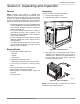
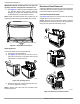


Table Of Contents
- Installation Guidelines 60 Hz Air-Cooled Generators
- Table of Contents
- Section 1: Safety Rules & General Information
- Section 2: Unpacking and Inspection
- Section 3: Site Selection and Preparation
- Section 4: Generator Placement
- Section 5: Fuel Conversion / Gas Connections
- Section 6: Electrical Connections
- Section 7: Control Panel Startup / Testing
- Section 8: Troubleshooting
- Section 9: Quick Reference Guide
- Section 10: Accessories
- Section 11: Diagrams

Unpacking and Inspection
Installation Guidelines for 60 Hz Air-Cooled Generators 11
Auxiliary Shutdown Switch
All generators are equipped with an external means of
shutting down the generator which complies with the lat-
est NEC code requirement. The primary generator shut-
down sequence is described in Control Panel Startup /
Testing.
See Figure 2-11. An auxiliary shutdown switch (A) is
located on the exterior of the generator back panel. This
switch shuts down the generator and disables restarts.
Figure 2-11. Auxiliary Shutdown Switch (all models)
NOTE: Whenever possible, perform primary shutdown
procedure before disabling generator with auxiliary shut-
down switch.
See Figure 2-12. 14–24 kW generators have an auxiliary
shutdown switch (B) located inside the generator.
Figure 2-12. Auxiliary Shutdown Switch (14–24 kW)
NOTE: Generator will not start if either switch is OPEN
(O). Controller displays an “Auxiliary Shutdown” alarm,
and red LED “Alarm” light illuminates until switch or
switches are CLOSED (I) and alarm is cleared by press-
ing OFF mode button, and then ENTER. Once cleared,
generator can be placed back in AUTO or MANUAL.
Equipment Damage. The auxiliary shutdown switch
is not to be used to power down the unit under
normal operating circumstances. Doing so will
result in equipment damage.
(000399)
CAUTION
005491
A
005492
B