
User Manual


wall will cause diraction, which leads to
inferior frequency response and stereo
image. Ensure that the enclosure is ush
with the surface of the wall.
If a decorative cloth frame is used to
cover the wall, make sure that the edges
adjacent to the monitor are less than 20
mm (3/4 in) deep. The cloth must be very
thin Tricot or acoustically transparent
material, otherwise the high frequency
response of the system will be adversely
affected. Genelec approved cloth grilles
are available.
Recess for Cable
Connectors
The Speakon cable connectors extend 100
mm (4 in) from the rear panel of the monitor
enclosure. Therefore, a recess at least 100
mm (4 in) deep must exist to allow for the
cable behind the enclosure. The location
of the recess is shown in Fig. 5. Note that
the connectors are positioned o-centre.
Therefore, if the enclosure is rotated for a
left and right channel, the recess will be
at dierent heights on the left and right
side. This occurs when the enclosures are
mounted in the horizontal conguration.
Connecting Speaker Cables
Insert the connectors into the appropriate
sockets “WOOFER”, “MIDRANGE/
TWEETER” and “LED CONNECTOR” found
on the rear panel of the amplier unit and
the rear of the monitor enclosure. Note
that each RAM-XL amplier is individually
calibrated for use with the enclosure that it
is delivered with and marked with the same
serial number. Do not mix these amplier/
enclosure pairs.
Insert the connectors into the sockets
and turn the connectors clockwise.
The connectors lock automatically. The
electrical connections are only made when
the connectors are fully inserted.
To remove the signal connectors pull
the release lever on the connector and
turn the connector counterclockwise
simultaneously. The connector can now be
removed from the socket.
Set-up and Use
The 1236A is set up using the GLM
software. The setup is fast and consists of
the following steps:
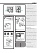
Figure 6. GLM network cabling (audio cabling not shown)
• Link all monitors and subwoofers in a
daisy-chain by running CAT5 (RJ45)
network cables from the Network
Adaptor to the "CONTROL NETWORK"
connectors of the RAM-XL modules,
and then on to the remaining monitors
in the controls room. The actual order
of the daisy-chain is not important,
such that if the computer is in the
control room and the RAM-XL modules
are in a machine room, they can be
networked last in the chain.
• Run the nal network cable to control
network input of the GLM Adapter
device.
• Connect the GLM Adapter device to
your computer USB connector. The
cable is a part of the GLM User Kit.
• Place the Genelec measurement
microphone at the listening location
of the engineer, on a stand, with the
microphone pointing upwards and
the microphone top at the height of
the engineers ear in normal working
position. The microphone is a part of
the GLM User Kit.
• Run the microphone cable to the
microphone input in the GLM Adapter
device.
• Download GLM software at the
Genelec web site (www.genelec.com).
Install the GLM software.
• Follow the GLM software instructions
to measure and set up your monitors.
• If you plan not to use a computer for
controlling the monitors, use the GLM
software to write the settings into the
monitors ("Store the Settings").
Recommendations for
AES/EBU Audio
For a digital input signal of –30 dB FS,
the 1236A monitors will produce a 100 dB
sound level (SPL) at 1 meter distance, in
free space. The sensitivity of the monitor
system is set using the GLM software.
It is advantageous to keep the maximum
incoming digital audio signal level high,
near to 0 dBFS. It may be useful to lower
the internal GLM level control. This enables
maintaining high digital resolution in the
digital source.
LISTENING
POSITION
MICROPHONE
GLM
NETWORK
GLM
NETWORK
GLM
NETWORK
USB
RAM-XL RAM-XL