
User's Manual
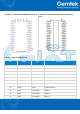
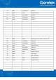
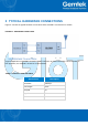

FIGURE 1-1: GL6509 SMT PIN DIAGRAM(Top View)
FIGURE 1-2: GL6509 PIN HEADER PIN DIAGRAM(Top
View)
TABLE 1-2: SMT PIN DESCRIPTION
Pin
Name
Type
Description
1
GND
Power
System Ground
2
N.C.
---
Not Connected
3
PB8
Input/Output
GPIO_1
4
GND
Power
System Ground
5
GND
Power
System Ground
6
GND
Power
System Ground
7
BOOT0
Input
Reserved for debug. Not Connected.
8
GND
Power
System Ground
9
PA3
Input/Output
GPIO_2
10
PA2
Input/Output
GPIO_3
11
PB6
Input/Output
GPIO_4