
User's Manual
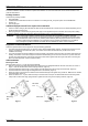
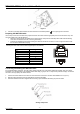
Table Of Contents
- Package Content
- Additional Equipment and Tools required for Installation
- Equipment Location Guidelines
- ODU Installation
- Preparing the IDU-ODU Cable
- Connecting and Sealing the IDU-ODU Cable
- NG_VG Installation
- Basic Configuration
- Aligning the ODU's Antenna
- Verifying Proper Operation
- Radio Frequency Interference Statement
- Radiation Hazard Warning
- R&TTE Compliance Statement
- Disposal of Electronic and Electrical Waste

PRO 3000 CPE Quick Installation Guide
- 1 -
T
his Quick Installation Guide is intended for experienced installers. For more information refer to the relevant sections in the
CPEs Product Manual.
Package Content
Check that the package contains:
PRO 3000 ODU
Crossed Ethernet cable with two RJ-45 connectors for connecting the NG_VG power injector to a PC/HUB/switch.
Sealing cap
Pole mounting kit
Additional Equipment and Tools required for Installation
Indoor-to-outdoor Category 5E PoE Ethernet cable with two shielded RJ-45 connectors (can be ordered separately) and an
RJ-45 connectors crimping tool.
Mains plug adapter or termination plug (if the power plug on the supplied AC power cord does not fit local power outlets).
Sealing materials: mastic tape (Scotchfil™ Electrical Insulation Putty), Cold Shrink sealing kit.
WARNING:
ONLY experienced installation professionals who are familiar with local building and safety codes and,
wherever applicable, are licensed by the appropriate government regulatory authorities should install outdoor
units and antennas. Failure to do so may void the product warranty and may expose the end user or Service
Provider to legal and financial liabilities. The manufacturer and its resellers or distributors are not liable for
injury, damage or regulation violations associated with the installation of outdoor units or antennas.
Equipment Location Guidelines
Select the optimal locations for the equipment using the following guidelines:
1. The antenna should provide a direct, or near line of sight, with the Base Station antenna. The higher the placement of the
antenna, the better the achievable link quality. The location of the ODU should enable easy access to the unit for
installation and testing.
2. The indoor equipment should be installed as close as possible to the location where the indoor-to-outdoor cable enters the
building. The location of the indoor equipment should be selected taking into account its connection to a power outlet and
the end-user’s data equipment. (The length of the IDU-to-ODU cable, together with the length of the cable connecting the
IDU to the data equipment, should not exceed 100m).
ODU Installation
Mounting the ODU
Mount the ODU unit on a 1"-4" pole using the supplied kit:
1. With the connector facing downward, attach the bracket to the two designated holes at the back of the ODU, as shown in
Figure 1. Use the two M5*16mm bolts and spring washers. (Figure 1)
2. Thread the M8*40mm bolt through a spring washer and a flat washer and then through the bracket hole. (Figure 2)
3. Thread the M5*35mm bolt through the designated hole in the bracket. (Figure 2)
4. Attach the clamp to the bracket such that the bolt is threaded through it and tighten using an M8 nut. Make sure the bracket
is secured tightly. (Figure 3)
5. Attach the ODU to a 1" -4" pole. Attach the clamp to the other side of the pole. Thread the M8*100mm bolts through both
clamp holes on either side using spring washers. Tighten the bolts using nuts and spring washers. (Figure 4)
Figure 1 Figure 2 Figure 3
ODU
M8*40mm
bolt
Bracket
Clamp
M5*3
5 bolt
M5*16mm
B
o
l
t
M8 nut
P/N: 215805