
User Manual Part 2

User’s Guide Version 1.0
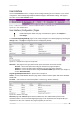
For example, there are 2 internal networks: network A and B, and intermediate network - Internet.
Network A (administrator's computer with Network Management System); we shall call this network
(192.168.82.0/24) “Net A”.
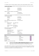
Network: 192.168.82.0
Netmask: 255.255.255.0
Router: 192.168.82.16
GRE server has two interfaces, LAN and WAN:
LAN IP: 192.168.82.16
WAN IP: 211.139.210.123
Network B has subscribers on LAN of BW1330 interface (ixp0) we shall call this network
(192.168.3.0/24) “Net B”:
Network: 192.168.3.0
Netmask: 255.255.255.0
Router: 192.168.3.1
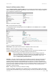
Where GRE interface (WAN IP of AC) is 211.139.210.168.
GRE server
Remote Host IP: 211.139.210.168
Interface IP: 0.0.0.0
Interface netmask: 255.255.255.0
Route: 192.168.3.0/24
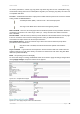
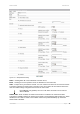
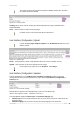
Refer to figure 125 the setting as below:
The setting of BW1330
GRE Remote Host IP: 211.139.210.123
GRE Interface IP: 0.0.0.0
GRE Interface netmask: 255.255.255.0
GRE Route: 192.168.82.0/24
Figure 125 – GRE client for VPN setting
The remote host IP address of “GRE client for VPN” is different with remote IP of
GRE service under Network Interface | Tunnels | PPPoE/GRE menu. You must
assign different IP address for the both GRE service enabled simultaneously.
As far as the Internet is concerned, we assume that it will pass any packet sent from Net A to Net B or
Net B to Net A. The administrator from Net A will be able to access clients on Net B through the GRE
tunnel between the GRE server and the GRE interface of AC.
BROWAN Page
79