
User Manual Part 1

User’s Guide Version 1.0
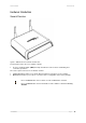
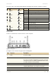
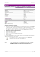
The various states of the LEDs indicate different networking and connection operations as follows:
Item LED Color Status Indication
On system is active/working Green
Blinking system is booting
1 Power
Orange On Writing to FLASH memory
On PPPoE/PPTP/GRE tunnel for DSL is actived. 2 Online Green
Off PPPoE/PPTP/GRE tunnel for DSL is deactived.
On WAN active/working 3 WAN Green
Blinking Data transmitting
On 100 Mbps network connection exists Green
Blinking Data transmitting
On 10 Mbps network connection exists
4 LAN
Orange
Blinking Data transmitting
On WLAN active/working 5
WLAN Green
Blinking Data transmitting
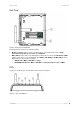
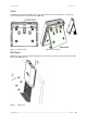
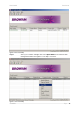
Connectors
The Access Controller has several connectors on the rear panel:
Figure 4 – Connectors
Descriptions of the connectors are given in the following table:
BROWAN Page
13
Item Connector Description
Power For power supply 1
2 Reset
Reboot or reset to factory defaults.
Press the reset button for less than 3 seconds to reboot the
controller. Press the reset button for more than 10 seconds
to set the controller to factory defaults
3 WAN For Internet connection and PoE input
4 LAN
For enterprise applications use this port to connect your
company LAN, Intranet or to hotspot access points
5 RS232 Console port
6 Antenna The MAIN antenna
7 Antenna The AUX antenna