7 Firewall Setup Overview Purpose This chapter explains how to configure the firewall for the CellPipe 7130 RG. Click the Firewall drop-down menu to open the Firewall Setup menu.
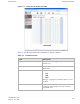
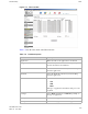
Firewall Setup Port Range Forwarding ............................................................................................................................................................................................................................................................ Figure 7-1 Port Range Forwarding window Table 7-1 describes the fields of the Port Range Forwarding window.
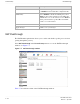
Firewall Setup Virtual Server Basic ............................................................................................................................................................................................................................................................ Field Description Apply Changes Click to save your changes. Virtual Server Basic The virtual server acts as a gateway to pass your service request from the Internet client to your LAN servers.
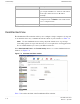
Firewall Setup Virtual Server Advance ............................................................................................................................................................................................................................................................ Field Description Apply Changes Click to save your changes. Add Application Application Enter the name of an application you are hosting on your LAN PC.
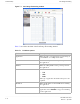
Firewall Setup Virtual Server Advance ............................................................................................................................................................................................................................................................ Figure 7-3 Virtual Server Advance window Table 7-3 describes the fields of the Virtual Server Advance window.
Firewall Setup Demilitarized Zone ............................................................................................................................................................................................................................................................ Field Description IP Address Enable the radio button in the left column to select a pre-configured LAN host or enable the radio button in the right column and enter an IP address manually.
Firewall Setup UPnP ............................................................................................................................................................................................................................................................ Table 7-4 Field descriptions Field Description Demilitarized Zone (DMZ) Select Enable to turn on the demilitarized zone function. Select Disable to turn it off.
Firewall Setup Filter ............................................................................................................................................................................................................................................................ Table 7-5 Field descriptions Field Description UPnP Select Enable to connect the UPnP function. Select Disable to disconnect the UPnP function. UPnP Log Select Enable to enable the logging activities.
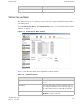
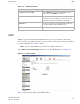
Firewall Setup Filter ............................................................................................................................................................................................................................................................ Figure 7-6 Filter window Table 7-6 describes the fields of the Filter window. Table 7-6 Field descriptions Field Description Application Enter the name of the application to be filtered.
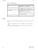
Firewall Setup NAT Passthrough ............................................................................................................................................................................................................................................................ Field Description Enable Select Enable to apply this filter configuration rule or Disable to turn off this filter configuration rule. DSCP Policy Select Disable to disable the DSCP policy.
Firewall Setup URL Filter ............................................................................................................................................................................................................................................................ Table 7-7 Field descriptions Field Description IPSec Passthrough Select the Enable radio button to allow IPSec passthrough. Select Disable to not allow the IPSec passthrough.
Firewall Setup URL Filter ............................................................................................................................................................................................................................................................ Table 7-8 Field descriptions Field Description Application Enter a name for the URL filter. URL Enter a URL or keyword of the URL you are blocking. If the keyword is too general, you might inadvertently block other websites.
8 Advanced Setup Overview This chapter explains how to configure the advanced settings of the CellPipe 7130 RG such as the route setting, bridge MAC filter, dynamic DNS, and system log. Click the Advanced Setup drop-down menu to open the Advanced Setup menu.
Advanced Setup Route Setting ............................................................................................................................................................................................................................................................ Figure 8-1 Route Setting window Table 8-1 describes the fields of the Route Setting window.
Advanced Setup Bridge MAC Filter ............................................................................................................................................................................................................................................................ Field Description Dynamic Route (WAN) Select Enable to use dynamic routing instead of static. Dynamic routing enables the router to adapt to changes in the path to the other network.
Advanced Setup Dynamic DNS ............................................................................................................................................................................................................................................................
Advanced Setup System Log ............................................................................................................................................................................................................................................................ Figure 8-3 Dynamic DNS window Table 8-3 describes the fields of the Dynamic DNS window. Table 8-3 Field descriptions Field Description DDNS Service If you have enabled your DDNS, select your DDNS service.
Advanced Setup System Log ............................................................................................................................................................................................................................................................ Figure 8-4 System Log window Table 8-4 describes the fields of the System Log window. Table 8-4 Field descriptions Field Description Log Size (Lines) Select the number of lines to display in your log.
Advanced Setup System Log ............................................................................................................................................................................................................................................................ Field Description Message The details of the action that was performed. ..........................................................................................................................................................
Advanced Setup System Log ............................................................................................................................................................................................................................................................ ......................................................................................................................................................................................................................................
9 QoS Setup Overview This chapter explains how to configure the quality of service (QoS) settings of the CellPipe 7130 RG. QoS is the ability to provide better service to selected applications and data flows. Click the QoS Setup drop-down menu to open the QoS Setup menu.
QoS Setup QoS IP Policy ............................................................................................................................................................................................................................................................ Figure 9-1 QoS Scheduler window Table 9-1 describes the fields of the QoS Scheduler window. Table 9-1 Field descriptions Field Description QoS Enable Select Enable to activate the QoS scheduler.
QoS Setup QoS IP Policy ............................................................................................................................................................................................................................................................ Figure 9-2 QoS IP Policy window Table 9-2 describes the fields of the QoS IP Policy window. Table 9-2 Field descriptions Field Description IP Enter the IP address of the source host and the destination host.
QoS Setup QoS ALG ............................................................................................................................................................................................................................................................ Field Description New Tos Value Enable New Tos Value and enter a queue number (0 to 7) to assign to the incoming traffic. New DSCP Value Enable New DSCP Value and enter a DSCP value (0 to 63).
QoS Setup QoS ALG ............................................................................................................................................................................................................................................................ Figure 9-3 QoS ALG window Table 9-3 describes the fields of the QoS ALG window. Table 9-3 Field descriptions Field Description SIP ALG QoS Enable Select Enable to turn on the SIP and ALG QoS.
QoS Setup QoS ALG ............................................................................................................................................................................................................................................................ Field Description Apply Changes Click to save your changes. ..............................................................................................................................................................................
10 Telephony Overview The CellPipe 7130 RG Telephony menu enables you to configure the settings for your VoIP account, service, server, and call list. Click the Telephony drop-down menu to open the Telephony menu. Contents This chapter covers the following topics. Account Setting 10-1 Service Setting 10-2 Server Setting 10-4 Call List 10-6 Account Setting The VoIP account settings can be configured from the account setting section of the telephony menu.
Telephony Service Setting ............................................................................................................................................................................................................................................................ Figure 10-1 Account setting window Table 10-1 describes the fields of the Account Setting window. Table 10-1 Field descriptions Field Description Configuration of Account Select a VoIP account to configure.
Telephony Service Setting ............................................................................................................................................................................................................................................................ Note: Changes made to the service settings apply to all VoIP accounts. It is recommended that you contact your VoIP service provider for assistance with configuring the service settings.
Telephony Server Setting ............................................................................................................................................................................................................................................................ Field Description Three-Way Conference Enable Active to enable the conference call. Message Wait Indication Enable Active to turn on the message wait indicator.
Telephony Server Setting ............................................................................................................................................................................................................................................................ Figure 10-3 Server Setting window Table 10-3 describes the fields of the Server Setting window. Table 10-3 Field descriptions Field Description SIP Registrar Address Enter the IP address of the SIP registration server.
Telephony Call List ............................................................................................................................................................................................................................................................ Call List The Call List window displays the call statistics and call log of your VoIP accounts. Select Call List in the Telephony menu to access the Call List window; see Figure 10-4.
11 Utilities Overview This chapter explains how to configure the utilities of the CellPipe 7130 RG. Click the Utilities drop-down menu to open the Utilities menu.
Utilities Configuration Backup ............................................................................................................................................................................................................................................................ Figure 11-1 Restore Factory Defaults window Click on Restore Defaults to restore the CellPipe 7130 RG to the factory default settings.
Utilities Configuration Restore ............................................................................................................................................................................................................................................................ Figure 11-2 Configuration Backup window Click on Backup to save your system configuration. Configuration Restore The Configuration Restore window enables you to restore your configuration of the CellPipe 7130 RG.
Utilities Web Firmware Upload ............................................................................................................................................................................................................................................................ Figure 11-3 Configuration Restore window Table 11-1 describes the fields of the Configuration Restore window.
Utilities Remote Management ............................................................................................................................................................................................................................................................ Figure 11-4 Web Firmware Upload window Table 11-2 describes the fields of the Web Firmware Upload window.
Utilities Remote Management ............................................................................................................................................................................................................................................................ Figure 11-5 Remote Management window Table 11-3 describes the fields of the Remote Management window.
Utilities System Setting ............................................................................................................................................................................................................................................................ Field Description Apply Changes Click to save your changes.
Utilities Management Access ............................................................................................................................................................................................................................................................ Field Description Type in Admin Current Password Enter the current admin password. Note: If this is the first time the admin password is changed, the default admin password is admin.
Utilities Reboot Gateway ............................................................................................................................................................................................................................................................ Figure 11-7 Management Access window Table 11-5 describes the fields of the Management Access window.
Utilities Connection Test ............................................................................................................................................................................................................................................................ Select Reboot Gateway in the Utilities menu to access the Reboot Gateway window; see Figure 11-8. Figure 11-8 Reboot Gateway window Click on Reboot to restart the CellPipe 7130 RG.
Utilities Connection Test ............................................................................................................................................................................................................................................................ Figure 11-9 Connection Test window Figure 11-6 describes the fields of the Connection Test window.
Utilities Connection Test ............................................................................................................................................................................................................................................................ ......................................................................................................................................................................................................................................
A Troubleshooting Overview This section identifies common problems that can arise during the use of the CellPipe 7130 RG (and offers solutions). Most issues are identified by the LEDs on the front panel of the CellPipe 7130 RG. Troubleshooting Table Symptom Possible cause Solution Power LED does not come on after power is switched on. Outlet, power cord, or power adapter might be defective. • • DSL LED flashes slowly after connection is established.
Troubleshooting Overview ............................................................................................................................................................................................................................................................ Symptom Possible cause Solution Internet LED is off. Your device is unable to connect to the Internet. The device might not be configured properly or the network adapter driver might need to be updated.
B TCP/IP configuration Overview The following procedures provide TCP/IP configuration instructions for all supported operating systems. Windows Vista 1. 2. 3. 4. 5. 6. 7. Open Network and sharing Center from the Control Panel. Open Manage network connections from the Network and sharing Center. Right-click Ethernet connection and select Properties. Under the General tab, select Internet Protocol (TCP/IPv4), and click Properties. Select the Obtain an IP address automatically radio button.
TCP/IP configuration Overview ............................................................................................................................................................................................................................................................ 4. Select the Obtain an IP address automatically radio button. 5. Select the Obtain DNS server address automatically radio button. 6. Click OK to save the settings. END OF STEPS ................................................
C Product conformance Overview This section lists the product conformance requirements for the EU. EU declaration of conformity This device complies with the essential requirements of the R&TTE Directive 1999/5/EC.
Product conformance EU declaration of conformity ............................................................................................................................................................................................................................................................ This device is a 2.4 GHz wideband transmission system (transceiver), intended for use in all EU member states and EFTA countries, except in France and Italy where restrictive use applies.
Federal Communication Commission Interference Statement This equipment has been tested and found to comply with the limits for a Class B digital device, pursuant to Part 15 of the FCC Rules. These limits are designed to provide reasonable protection against harmful interference in a residential installation. This equipment generates, uses and can radiate radio frequency energy and, if not installed and used in accordance with the instructions, may cause harmful interference to radio communications.
FCC REQUIREMENTS This equipment complies with Part 68 of FCC Rules and the requirements adopted by the ACTA.. On the bass unit of this equipment is a label that contains, among other information, a product identifier in the format US: GEMDL01B WVDK118. If requested, this number must be provided to the telephone company. The REN for this product is part of the product identifier that has the format US: GEMDL01B WVDK118. The digits represented by 01 are the REN without a decimal point.
Glossary Numerics 10/100Base-T The most widely used standard for Ethernet over twisted pair or copper-based computer networking. Runs at 10 Mb/s, 100 Mb/s, and 1000 Mb/s (1 Gb/s) respectively. 802.1 Q/P The standard that allows multiple bridged networks to transparently share the same physical network link without leakage of information between networks.
Glossary ............................................................................................................................................................................................................................................................
Glossary ............................................................................................................................................................................................................................................................ L L2TP Layer 2 tunneling protocol; a tunneling protocol used to support virtual private networks (VPNs). LAN Local Area Network M MAC Media Access Control Mb Megabit; a unit of information commonly used to express the rate data is transferred.
Glossary ............................................................................................................................................................................................................................................................ PSK Pre-Shared Key Q QoS Quality of Service R RJ-11 A physical interface often used for terminating telephone wires. RJ-45 Most regularly used as an Ethernet connector. RJ-45 connectors are typically used to terminate twisted pair cable.
Glossary ............................................................................................................................................................................................................................................................
Glossary ............................................................................................................................................................................................................................................................ .........................................................................................................................................................................................................................................................