
User's Manual
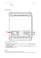
Table Of Contents

P-720 User’s Guide v1.0 Jun 10, 2005
Page 8 of 51
This chapter provides installation instructions for the hardware and software components of the
Access Point P-720. It also includes the procedures for the following tasks:
Hardware Introduction (LEDs, Connectors)
Connecting the Access Point
First Configuration
The Product Package
The product comes with the following:
Dual Radio Access Point (model: P-720)
Screw Bag for Mounting Kit
Antenna (Dual-band Dipole Antennas with TNC plug connector, 2 units)
Ethernet patch cable (Cat5 UTP, 1.8m length, 1 unit)
External power supply (Input:100-230VAC, 50-60Hz, Output: 12VDC, 1 unit)
Installation CD containing:
P-720 User Guide in PDF format
Product Firmware
Release Notes
Adobe Acrobat Readers
Readme
Printed Release Note
Hardware Introduction
General Overview
Figure 1 – P-720 General View
The front panel of P-720 contains:
There are 4 indicator lights (LEDs) that help to describe the state of various networking and
connection operations.
The Bottom cover of P-720 contains:
Connectors which enable you to make different network connections for the device
Reset button enables you to reboot or reset the device configuration to the factory defaults
Press the Reset button for less than 5 seconds to reboot the device.
Press the Reset button for more than 5 seconds to set the device to factory
Chapter 2 - Installation