
User's Manual
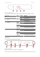
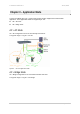
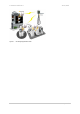
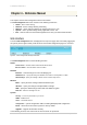
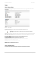
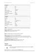
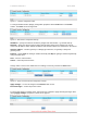
Table Of Contents

P-720 User’s Guide v1.0 Jun 10, 2005
Page 10 of 51
Figure 3 – LEDs of the P-720
The various states of the LEDs indicate different networking and connection operations as follows:
Item LED Color Status Indication
On P-720 is active/working 1 Power Green
Blink P-720 is booting
On P-720 Ethernet Port Link Active 2 LAN Green
Blink
P-720 Ethernet Port is Transmitting
and Receiving data
On P-720 WLAN1 RF card Active Green
(802.11g
module is
functional)
Blink
P-720 WLAN1 RF card is
Transmitting and Receiving data
On P-720 WLAN1 RF card Active
3 Wireless1
Amber
(802.11a
module is
functional)
Blink
P-720 WLAN1 RF card is
Transmitting and Receiving data
On P-720 WLAN2 RF card Active Green
(802.11g
module is
functional)
Blink
P-720 WLAN2 RF card is
Transmitting and Receiving data
On P-720 WLAN2 RF card Active
4 Wireless2
Amber
(802.11a
module is
functional)
Blink
P-720 WLAN2 RF card is
Transmitting and Receiving data
Connectors
The P-720 has several connectors on the rear panel:
Figure 4 –RF Connectors
Descriptions of the connectors are given in the following table:
1
2 3
4
1 23 4 5 6