Dual Radio 2.4GHz/5GHz Access Point P-720 User’s Guide v1.
Within the 5.15 to 5.25 GHz band (5GHz radio channels 34 to 48) the U-NII devices are restricted to indoor operations to reduce any potential harmful interference to MSS operations. FCC Warning FCC Interference Statement This equipment has been tested and found to comply with the limits for a Class B digital device, pursuant to Part 15 of the FCC Rules. These limits are designed to provide reasonable protection against harmful interference in a residential installation.
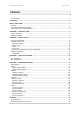
P-720 User’s Guide v1.0 Jun 10, 2005 Contents FCC Warning....................................................................................................................................... 1 CONTENTS ............................................................................................................................................ 2 ABOUT THIS GUIDE.............................................................................................................................. 4 Purpose ..........
P-720 User’s Guide v1.0 Jun 10, 2005 C) Regulatory Channels/Power ........................................................................................... 46 D) Location ID and ISO Country Codes ............................................................................................
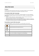
P-720 User’s Guide v1.0 Jun 10, 2005 About this Guide Purpose This document provides information and procedures on hardware installation, setup, configuration, and management of the high performance Dual Radio 2.4GHz/5GHz AP P-720. Prerequisite Skills and Knowledge To use this document effectively, you should have a working knowledge of Local Area Networking (LAN) concepts and wireless Internet access infrastructures.
P-720 User’s Guide v1.0 Jun 10, 2005 Chapter 1 – Introduction Thank you for choosing the Dual Radio Access Point P-720. The P-720 operates simultaneously in the 5-GHz and 2.4-GHz frequency bands and is fully compliant to 802.11b/g and 802.11a standard with its high performance and enhanced security. The two Dual-Band radio (a/g + a/g) that this product provides supplies the furthest in flexibility and makes sure low interference and large coverage.
P-720 User’s Guide v1.0 Jun 10, 2005 The P-720 can be remote managed by HTTPs, CLISH and SNMP.
P-720 User’s Guide v1.0 Jun 10, 2005 DHCP Server Super Brige 802.
P-720 User’s Guide v1.0 Jun 10, 2005 Chapter 2 - Installation This chapter provides installation instructions for the hardware and software components of the Access Point P-720.
P-720 User’s Guide v1.0 Jun 10, 2005 defaults. Bottom Cover 1 2 3 Figure 2 –Bottom Cover of the P-720 The Bottom Cover of the P-720 contains: 1. Back Label with Model and Device name. The official device name is Dual Radio 2.4GHz/5GHz Access Point, model P-720. 2. MAC address labels of the device. The two labels show the WLAN1 and WLAN2 interface MAC address of the device. 3. Serial Number label of the device.
P-720 User’s Guide v1.
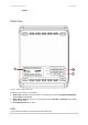
P-720 User’s Guide v1.0 Jun 10, 2005 Item Connector Description 1 WLAN1 For WLAN1 RF card connecting to Antenna 2 WLAN2 For WLAN2 RF card connecting to Antenna 3 Power For power supply 4 Reset Reboot or reset to factory defaults. Press the reset button for less than 5 seconds to reboot the Access Point. Press the reset button for more than 5 seconds to set the Access Point to factory defaults.
P-720 User’s Guide v1.0 Jun 10, 2005 Step 1 Place the Access Point on a flat work surface or hang on the wall. Step 2 Use the enclosed Ethernet patch cable to connect the LAN port of the Access Point to the Switch or hub in the local network. Step 3 Connect the power supply to the Access Point. Software Installation Initialization For the first web browser connection to your P-720, please use your Web browser The default network settings for your new access point are: LAN port: Step 1 IP 192.168.
P-720 User’s Guide v1.0 Step 3 Jun 10, 2005 After successful administrator log on you will see the main page of the P-720’s Web interface: Now you are enabled to perform your configuration.
P-720 User’s Guide v1.0 Jun 10, 2005 Chapter 3 – Application Mode The two Dual-Band chips (a/g + a/g) that this product provides supplies the furthest flexible application. Three application modes are supplied by P-720: z AP + AP mode z AP + Bridge mode AP + AP Mode AP + AP configuration can be for client density environment. The typical usage is: 11g AP + 11a AP. Figure 6 – AP +AP application mode AP + Bridge Mode AP + Bridge configuration is for environment with last mile issue.
P-720 User’s Guide v1.
P-720 User’s Guide v1.0 Jun 10, 2005 Chapter 4 – Reference Manual This chapter contains web management reference information. The web management main menu consists of the following sub menus: Status – device status showing Network – device settings affecting networking Wireless – device settings related to the wireless part of the P-720 System – device system settings directly applicable to the P-720 Exit – click exit and leave the web management then close your web-browser window.
P-720 User’s Guide v1.0 Jun 10, 2005 Status Status | Device Status The device status page shows important information for the P-720, its system status and network configuration. Figure 9 – Device Status System Version display the current version of the firmware loaded to the AP This is important information for support requests and for preparing firmware upgrading Uptime indicates the time, expressed in days, hours and minutes since the system was last rebooted.
P-720 User’s Guide v1.0 Jun 10, 2005 US US Figure 10 – Wireless Status Radio1 / Radio2 relates with two wireless interfaces Channel indicates which channel is in use.
P-720 User’s Guide v1.0 Jun 10, 2005 Figure 11 – Interface Configuration Table To change network interface (bridge) configuration properties click the Edit button in the Action column. The status can be changed now: Figure 12 – Edit Interface Configuration Settings IP Address - specify new interface IP address [in digits and dots notation, e.g. 192.168.123.70]. Netmask – specify the subnet mask [[0-255].[0-255].[0-255].[0-255]].
P-720 User’s Guide v1.0 Jun 10, 2005 Figure 14 – Reboot Server Reboot – Click the button to restart the server and apply the changes. If there is no other setting needed to be modified, click the Reboot button for applying all modifications. And if there are still other setting modifications needed, go ahead to finish all changes and then click Reboot button to restart and apply all settings together. To reboot at once, click Reboot button and then it is necessary to wait a moment.
P-720 User’s Guide v1.0 Jun 10, 2005 Figure 16 – RADIUS Servers Settings Add – add new RADIUS server. Click Add to configure RADIUS server settings. Figure 17 – RADIUS Server's Details Name – specify the new RADIUS server name which is used for selecting RADIUS server. Server IP – authentication RADIUS server IP address [dots and digits]. Server Port – specify the network port used to communicate with RADIUS [1-65535].
P-720 User’s Guide v1.0 Jun 10, 2005 DHCP server and DHCP relay is disabled by default. Figure 18 –DHCP Settings Edit – edit the wireless basic settings To change DHCP setting properties click the Edit button, the DHCP server or DHCP relay service should be configured: Figure 19 –DHCP Settings Status – Select status from the drop-down menu. Disabled – Disable the DHCP server service. DHCP Server – Enable the DHCP server service. DHCP Relay – Enable the DHCP Relay service.
P-720 User’s Guide v1.0 Jun 10, 2005 By default, DHCP server is disabled for P-720. IP Address from / IP Address to – specify the IP address range to be dynamically allocated by the DHCP server. Netmask – enter the netmask for IP pool range. Gateway – enter the gateway IP for wireless clients. WINS Address (Windows Internet Naming Service) – specify server IP address if it is available on the network [dots and digits]. Lease Time – specify the IP address lease interval in seconds [1-1000000].
P-720 User’s Guide v1.0 Jun 10, 2005 Figure 22 – Reboot information Reboot – Click the button to restart the server and apply the changes. If there is no other setting needed to be modified, click the Reboot button for applying all modifications. And if there are still other setting modifications needed, go ahead to finish all changes and then click Reboot button to restart and apply all settings together.
P-720 User’s Guide v1.0 Jun 10, 2005 DHCP Relay To route DHCP through the external server, enable the DHCP Relay service. Figure 24 – DHCP Relay settings Server IP: enter the IP address of the external DHCP server. Change status or leave in the default state if no editing is necessary and click the Save button. Figure 25 –Apply or Discard DHCP relay Settings For each change of settings, the P-720 needs to be restarted to apply all settings changes when clicking Apply Changes.
P-720 User’s Guide v1.0 Jun 10, 2005 Wireless Wireless | Basic Use the wireless | Basic menu to configure such wireless settings as regulatory channel, band, and power, layer2isolation. Click the edit button on the setting you need to change: Figure 27 – Basic Wireless Settings Site Survey –perform survey to show overview information for wireless networks in a local geography. The site survey shows overview information for wireless networks in a local geographic area.
P-720 User’s Guide v1.0 Jun 10, 2005 Click OK to continue site survey and get the similar UI: Figure 29 – Site Survey information To refresh the statistics click the Rescan button. During Site Survey, all wireless clients which are connecting with P-720 would be kicked off. Site Survey takes some minutes to perform. Please wait and don’t power off AP during site survey. Edit – edit the wireless basic settings To change basic wireless setting properties click the Edit button in the Action column.
P-720 User’s Guide v1.0 Jun 10, 2005 Figure 31 – Apply or Discard Basic Wireless Settings Radio – specify which wireless interface of P-720 is shown Channels – select the channel that the access point will use to transmit and receive information. If one channel is defined, it acts as default channel. Channels list will vary depending on selected regulatory selected band. Multiple frequency channels are used to avoid interference between two radios of this AP, and between nearby access points.
P-720 User’s Guide v1.0 Jun 10, 2005 Total Output Power (EIRP) – the P-720 transmission output power (EIRP) in dBm. Seven levels are specified: 17dBm, 16dBm, 15dBm, 14dBm, 10dBm, 4dBm and 0dBm. Default is 14dBm. Total Output Power (EIRP) = Antenna Gain + RF card output power The range of the EIRP varies with channel. RTS Threshold – when set, this settings specifies the maximum packet size beyond which RTS/CTS mechanism is be invokes. The value range of this is [0 …2347].
P-720 User’s Guide v1.0 Jun 10, 2005 Wireless | Advance P-720 supports Multiple BSSID (MBSSID) function. You can configure up to 16 BSSIDs per radio on P-720 and assign different configuration settings to each BSSID. For wireless users, they can think P720 as single AP with multi service supporting, including different security policy, different VLAN ID, different authentication etc.
P-720 User’s Guide v1.
P-720 User’s Guide v1.0 Jun 10, 2005 Figure 35 – Multiple BSSID Setting Radio – showing which RF card (wlan1 or wlan2) is being configured. Mode – showing the current operation mode of P-720 (AP or Bridge). Interface – showing the current MBSSID | Bridge link entry SSID – a unique ID for your wireless network. It is case sensitive and must not exceed 32 characters. The default SSID is "P-720" but you should change this to a personal wireless network name.
P-720 User’s Guide v1.0 Jun 10, 2005 802.1p Tag – Configure 802.1p Tag for remote APC’s or Router’s QoS uses. Valid numbers are from 0 to 7. VLAN ID and 802.1p tag must cooperate with remote Router or APC. Security – Specify the security policy. WEP – When selected, the privacy of MSSID entry will be set to WEP (Wired Equivalent Privacy). WEP Key Index – Select the default key Index to make it the Default key and encrypt the data before being transmitted.
P-720 User’s Guide v1.0 Jun 10, 2005 Figure 36 – Advanced Wireless Setting (Bridge Mode) Radio – specify which RF card (wlan1 or wlan2) is needed to be configured since P-720 has two Dual-Band radios Mode – specify the operation mode of P-720 (AP or Bridge) Interface – Choose the specified Bridge link entry you want to configure.
P-720 User’s Guide v1.0 Jun 10, 2005 Figure 38 – Bridge Link Setting Remote MAC – Add the remote peer’s MAC address you want to configure as a bridge link Security – Specify WEP or WPA-PSK (TKIP or AES) is used for security policy. WPA-PSK or static WEP can be used for encrypt each bridge link Each Bridge link can have its own WEP key/keyIndex for encryption. Only WEP can be used as security policy for Bridge links now. More enhanced security policy is in developing.
P-720 User’s Guide v1.0 Jun 10, 2005 Radio – specify which RF card (wlan1 or wlan2) is needed to be set. Click Edit to edit the existing wepkey1 to wepkey4. By default, four WEP keys are all set to “aaaaa”. They can be modified according to real need. Figure 40 – Edit WEP Key Wireless | MAC ACL Use the MAC ACL service to control the default access to the wireless interface of the P-720 or define special access rules for mobile clients.
P-720 User’s Guide v1.0 Jun 10, 2005 Select Disabled means no ACL service. Figure 42 – MAC ACL settings You must create MAC List to work with Policy setting. The access control list is based on the network device’s MAC address. In the MAC ACL Configuration table, you only need to specify the MAC address of wireless client.
P-720 User’s Guide v1.0 Jun 10, 2005 Figure 45 – Reboot Server Reboot – Click the button to restart the server and apply the changes. If there is no other setting needed to be modified, click the Reboot button for applying all modifications. And if there are still other setting modifications needed, go ahead to finish all changes and then click Reboot button to restart and apply all settings together.
P-720 User’s Guide v1.0 Jun 10, 2005 System System | Security Use the System | Security service to configure the name and password administrator: Figure 46 – system security settings User Name – administrator username for access to P-720 (e.g. web interface, CLI mode) [1-32 symbols, spaces not allowed]. Old Password – old password value. New Password –new password value used for user authentication in the system [4-8 characters, spaces not allowed].
P-720 User’s Guide v1.0 Jun 10, 2005 Figure 47 – SNMP settings Readonly community – Community name is used in SNMP version 1 and version 2c. Read-only (public) community allows reading values, but denies any attempt to change values [1-32 all ASCII printable characters, no spaces]. Readwrite community – Community name is used in SNMP version 1 and version 2c. Read-write (private) community allows to read and (where possible) change values [1-32 all ASCII printable characters, no spaces].
P-720 User’s Guide v1.0 Jun 10, 2005 System | Telnet Use System | Telnet menu to manage the telnet/SSH service of your P-720. Figure 50 – System Configuration settings Telnet Service – Enable or disable telnet service of P-720 SSH Service – Enable or disable SSH service of P-720. The default of these two services are all Enabled. The current IETF SSH (SSHv2) is supported for security of accessing P-720 via telnet/CLISH.
P-720 User’s Guide v1.
P-720 User’s Guide v1.
P-720 User’s Guide v1.0 Jun 10, 2005 Figure 59 – Firmware Upgrade Click the Upload and then the follow appears. Specify the full path to the new firmware image and click the Upload button: Figure 60 – Firmware Upgrade To flash the uploaded firmware image to upgrade the firmware is done by click the Upgrade button. Please make sure the firmware is correct for P-720. Otherwise the upgrade will be failed.
P-720 User’s Guide v1.0 Jun 10, 2005 Appendix A) Specification Wireless Standard IEEE 802.11b(DSSS), IEEE 802.11g(OFDM) and IEEE 802.11a(OFDM) Data Rate 802.11a: 54,48,36,24,18,12,9,6Mbps;802.11g: 54,48,36,24,12,9,6,11,5,5,2,1Mbps (auto fall back) Turbo 802.11a: 108Mbps Transmit Power (adjustable RF power) Max. 17 dBm ± 1.5dBm @6~24Mbps Max. 13 dBm ± 1.
P-720 User’s Guide v1.0 Jun 10, 2005 B) Factory Defaults for the P-720 General Configuration Settings Administrator Username Administrator Password Get Community Set Community admin admin01 Public Private Network Configuration Settings IP address Subnet mask Gateway (static IP) 192.168.2.2 255.255.255.0 0.0.0.
P-720 User’s Guide v1.0 Jun 10, 2005 9 2452 • • • 10 2457 • • • 11 2462 • • • 12 2467 — • • 13 2472 — • • 14 2484 — — — Maximum output Power 18.5dBm 14dBm 14dBm For channel 1 and channel 11, the maximum output power will be 18.5dBm in the case of the setting of FCC.
P-720 User’s Guide v1.0 Jun 10, 2005 D) Location ID and ISO Country Codes This list states the country names (official short names in English) in alphabetical order as given in ISO 3166-1 and the corresponding ISO 3166-1-alpha-2 code elements. It lists 239 official short names and code elements.
P-720 User’s Guide v1.
P-720 User’s Guide v1.
P-720 User’s Guide v1.