
User Manual

User’s Guide Chapter 2 – Installation
Hardware Installation
Carefully select the ideal position for your Access Point by considering the following
recommendations:
The length of the Ethernet cable that connects the Access Point to the network must not exceed
100 meters.
Place the Access Point in a dry, clean location as far from the ground as possible, such as at the
top of a wall, keeping clear of metal obstructions.
Place the Access Point away from transformers, heavy-duty motors, fluorescent lights, microwave
ovens, refrigerators, or other equipment that could cause radio signal interference.
Locate the AP(s) so that the primary lobe provides coverage where it is required.
Don't cover the Access Point with material that absorbs the radio signal (e.g. wooden paneling,
walls).
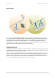
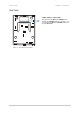
Attaching the Access Point to the Wall
Step 1 Place the Access Point at the desired location. Use the wall mounting assembly kit that is
delivered with the P-520r Access Point.
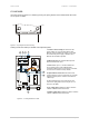
Step 2 Attach the wall mounting clamp to the wall with the spring latch to the upper side using
the four screws.
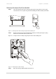
Step 3 Connect the rear side of the Access Point to the mounting plate:
Figure 6 – Attaching the P-520r Housing to the Mounting Clamp
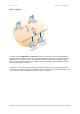
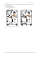
Step 4 Move the housing slightly downward and press until the spring latch is locked in place.
The P-520r Access Point is now securely mounted onto the wall and cannot be
removed without special tools.
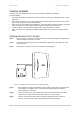
Step 5 Open the housing of the Access Point and connect an Ethernet cable to the RJ45
socket. Run the cable to the desired cable inlet then close the housing.
Step 6 Connect the twisted pair LAN cable to a Power-over-Ethernet device (switch or
injector). At least the power LED and the LAN link LED should light up.
Gemtek Systems Page 18