
User Manual

User’s Guide Chapter 2 – Installation
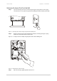
A Look Inside
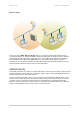
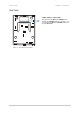
Open the housing of the Access Point by pressing the spring latches on the bottom back side of the
access point as shown:
Figure 3 – Opening the P-520r Housing
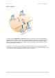
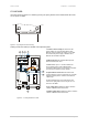
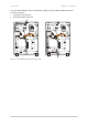
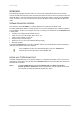
Looking inside the P-520r you will find some important points:
1. Power Connector Plug for external 5V DC
power supply. For use only when Power-over-
Ethernet is not available. We advise to use either
the external 5V power supply OR Power-over-
Ethernet but not both in parallel.
1 2 3 6
7
5
4
2. Ethernet Socket for common twisted pair or
Power-over-Ethernet cable.
3. Reset button: press 1 second to unlock the
Access Point and to set the administrator’s
password to default. Press more than 8 seconds to
reset the Access Point to factory default.
4.
I-pex Antenna Connectors for internal and
external antennas is the J4 connector. For use with
original Gemtek Systems antennas and antenna
cables only!
5. After installing the Access Point on the wall,
release the spring latch to Removing the Access
Point from the Wall.
6. Top Cable Inlet for Ethernet cable or antenna
cable for additional external antennas.
7. Bottom Cable Inlet for Ethernet cable or antenna
cable for additional external antennas.
Figure 4 – Looking Inside the P-520r
Gemtek Systems Page 16