54Mb Operator Access Point P-520r User’s Guide Revision 2.5 July, 2006 Copyright © 2002-2006 Gemtek Systems Holding BV www.gemtek-systems.
Copyright © 2002-2006 Gemtek Systems Holding BV. This user’s guide and the software described in it are copyrighted with all rights reserved. No part of this publication may be reproduced, transmitted, transcribed, stored in a retrieval system, or translated into any language in any form by any means without the written permission of Gemtek Systems Holding BV. Notice Gemtek Systems reserves the right to change specifications without prior notice.
FCC Warning R&TTE Compliance Statement This equipment has been tested and found to comply with the limits for a Class B digital device, pursuant to Part 15 of the FCC Rules. These limits are designed to provide reasonable protection against harmful interference in a residential installation.
User’s Guide Contents Contents Copyright ............................................................................................................................................. 3 Notice .................................................................................................................................................. 3 Trademarks .........................................................................................................................................
User’s Guide Contents Configuration | Wireless | WDS Links............................................................................................42 Configuration | Wireless | Advanced Settings................................................................................46 Configuration | Security | Wireless Security | Client Isolation........................................................47 Configuration | Security | Wireless Security | Access Control List..........................................
User’s Guide About this Guide About this Guide Purpose This document provides information and procedures on hardware installation, setup, configuration, and management of the Gemtek Systems 54Mbps Operator Access Point P-520r. Prerequisite Skills and Knowledge To use this document effectively, you should have a working knowledge of Local Area Networking (LAN) concepts and wireless Internet access infrastructures.
User’s Guide Chapter 1 – Introduction Chapter 1 – Introduction Thank you for choosing the Gemtek Systems 54Mbps Operator Access Point model P-520r. The Gemtek Systems P-520r is a Carrier-Grade Wi-Fi Access Point designed to provide reliable and secure wireless access to an operator network or enterprise LAN.
User’s Guide Chapter 1 – Introduction Management Options There are several managing and monitoring interfaces available to the operator to configure and manage the P-520r on your network: Web-browser Interface SNMP Management (SNMP v1, v2c) Gemtek Management System (GMS) This user manual provides detailed description of Web and SNMP management option.
User’s Guide Chapter 1 – Introduction DHCP client Remote software update SNMPv1, SNMPv2, incl. traps, MIB-II, IEEE-802.11, Gemtek general Private MIB Operating Modes The P-520r Access Point can work in different operating modes: Access Point (AP) mode: In AP mode the P-520r can connect multiple wireless client stations to a wired network. The Local Area Network and the Wireless Network are from the same IP address space.
User’s Guide Chapter 1 – Introduction Wireless Bridge: The first use of the WDS, Wireless Bridge mode is to create the wireless bridge between two or more wired networks, for example networks in different buildings with no wired connections between them. All APs in a WDS have to be configured for the same radio channel and must be configured with their WDS partner AP BSSIDs (MAC addresses). The data being transported is bridged transparently; i.e.
User’s Guide Chapter 1 – Introduction Wireless Repeater: The other use of the WDS, Wireless Repeater mode is to extend wireless area coverage between wired and wireless networks. This mode is normally used in large, open areas, where pulling a wire is prohibited or not cost effective and in residential circumstances. By settings up the BSSIDs (MAC addresses) between AP’s WDS partners, stations can intersect with any AP of this BSSID and move between the coverage of both APs.
User’s Guide Chapter 2 – Installation Chapter 2 – Installation This chapter provides installation instructions for the hardware and software components of the P-520r Operator Access Point.
User’s Guide Chapter 2 – Installation Hardware Introduction Front Panel: LEDs The Operator Access Point has three LED’s located on its front. 1. Power LED 2. LAN link LED 3.
User’s Guide Chapter 2 – Installation Rear Panel P520r 1. MAC Address of the P-520r MAC:00904B111698 1 This label shows the Wireless LAN MAC which coincide with LAN MAC address of the device. You can determine the Wireless LAN MAC address by using the KickStart.
User’s Guide Chapter 2 – Installation A Look Inside Open the housing of the Access Point by pressing the spring latches on the bottom back side of the access point as shown: Figure 3 – Opening the P-520r Housing Looking inside the P-520r you will find some important points: 1 2 3 1. Power Connector Plug for external 5V DC power supply. For use only when Power-overEthernet is not available. We advise to use either the external 5V power supply OR Power-overEthernet but not both in parallel. 6 2.
User’s Guide Chapter 2 – Installation You can feed the Ethernet cable, external power supply or antenna cable for additional external antennas in two ways: Through the top cable inlet Through the bottom cable inlet Figure 5 – Top and Bottom Cable Inlet of the P-520r Gemtek Systems Page 17
User’s Guide Chapter 2 – Installation Hardware Installation Carefully select the ideal position for your Access Point by considering the following recommendations: The length of the Ethernet cable that connects the Access Point to the network must not exceed 100 meters. Place the Access Point in a dry, clean location as far from the ground as possible, such as at the top of a wall, keeping clear of metal obstructions.
User’s Guide Chapter 2 – Installation Removing the Access Point from the Wall Step 1 Open the housing of the Access Point by pressing the spring latches on the upper rear side of the access point using the disassembling tool delivered with your P-520r: Figure 7 – Removing the P-520r Housing Using the Disassembling tool Step 2 Release the housing from the wall-mounting clamp by carefully pressing the spring latch in the center of the device (unit 5 in the Figure 4 – Looking Inside the P-520r) using th
User’s Guide Chapter 2 – Installation Initialization The following paragraphs describe how to access the web configuration interface of the Gemtek Systems P-520r. After unpacking and connecting the product for the first time it responds to either the default IP address 192.168.2.2/255.255.255.0 or to a dynamic IP address given by your local DHCP server. In the later case you need to locate the dynamic IP address of the P-520r with the KickStart utility.
User’s Guide Step 2 Chapter 2 – Installation Select your access point and right click.
User’s Guide Step 3 Chapter 2 – Installation Enter the P-520r administrator login details to access the web management interface.
User’s Guide Chapter 2 – Installation Reset to the Factory Default Settings Keep in mind that resetting the device is an irreversible process. Please note that even the administrator password will be set back to the factory default! If you have mis-configured your device in such a way that you cannot get access to modify its parameters via your Web browser you have two options to reset the device back to its factory default settings.
User’s Guide Chapter 2 – Installation Step 3 Enter the Temporary IP Address for your AP, e.g. 192.168.2.28 (address should be from the same subnet as local host) and click the OK: Step 4 After successful entry of a temporary IP address you can access your access point with the default administrator login. The access point system configuration (except temporary IP address) is left unchanged.
User’s Guide Chapter 3 – Quick Setup Chapter 3 – Quick Setup This chapter provides how to setup the P-520r Operator Access Point the step-by step. Setup Wizard To easily configure your access point step-by-step, choose the Setup Wizard from the main menu. With this wizard you are able to configure the following settings: Select the country and regulatory domain in which you will use the access point Specify IP addresses (static or dynamic) Define the radio policy (802.11b, 802.
User’s Guide Chapter 3 – Quick Setup Cancel – click to cancel the access point setup process. To continue the setup wizard click the Next button and choose the primary address selection. Step 2 Network Setup The IP configuration as described below is required for device management purposes. IP addresses can either be retrieved from a DHCP server or configured manually.
User’s Guide Chapter 3 – Quick Setup Figure 12 – Network Setup To find your P-520r with dynamic IP settings use the KickStart. Back – click return to the previous wizard page. Next – click to continue the access point setup process. Cancel – click to cancel the access point setup process. Step 3 Internal Radio Policy When the IP configuration is finished click the Next button and new page Internal radio policy is displayed. You can choose now the radio policy. It can be G-only (802.11g), B-only (802.
User’s Guide Chapter 3 – Quick Setup Figure 13 – Internal Radio Policy Settings Changing the radio policy could result in a loss of your connection when you are using a wireless connection. Mixed – select the mixed radio policy that allows both 802.11b and 802.11g modes. G-only – select the 802.11g mode to connect 802.11g clients only. B-only – select the 802.11b mode to connect 802.11g clients only. Back – click return to the previous wizard page. Next – click to continue the access point setup process.
User’s Guide Chapter 3 – Quick Setup Figure 14 – Network Identification Settings Wireless Network Name (SSID) – specify the unique name for your wireless network. Radio Channel – select the channel that the access point uses to transmit and receive information. Back – click return to the previous wizard page. Next – click to continue the access point setup process. Cancel – click to cancel the access point setup process.
User’s Guide Chapter 3 – Quick Setup Figure 15 – Security Settings Back – click return to the previous wizard page. Next – click to continue the access point setup process. Cancel – click to cancel the access point setup process. If you ant to choose WEP encryption, just select the Wired Equivalent Privacy (WEP) radio button and click Next button to configure the WEP encryption settings.
User’s Guide Chapter 3 – Quick Setup Back – click return to the previous wizard page. Next – click to continue the access point setup process. Cancel – click to cancel the access point setup process. To continue the setup wizard click the Next button and the new Administrator Password Setup page will appear.
User’s Guide Chapter 3 – Quick Setup Figure 18 – Administrator Password Setup Settings Password – enter the new password value used for user authentication in the system [4-32 symbols]. Confirm Password – re-enter the new password to verify its accuracy. Back – click to return to the main wizard page. Next – click to continue the access point setup process. Cancel – click to cancel the access point setup process.
User’s Guide Chapter 3 – Quick Setup Back – click to return to the previous wizard page. Finish – click to finish the access point setup process. Cancel – click to cancel the access point setup process. Click the Finish button to complete the quick setup wizard. The Access Point is now ready for basic operation. You can now use the web interface menu to configure many more details for your P-520r.
User’s Guide Chapter 4 – Reference Manual Chapter 4 – Reference Manual The following paragraphs describe capabilities and configuration parameters of the web management interface of the P-520r Operator Access Point. When the access point is installed you can access and configure the device using a standard web browser.
User’s Guide Chapter 4 – Reference Manual Configuration Configuration – identity data of the access point: Settings Summary – the summary of main access point settings Identity – name, location, operator of the access point Local Area Network – network interface configuration: Network Setup – IP address, netmask, gateway, Dynamic IP (DHCP) Virtual LAN – VLAN settings Wireless - wireless interface configuration: Basic Settings – SSID, channel selection and other settings WDS Links – configuration of Wire
User’s Guide Chapter 4 – Reference Manual Configuration Configuration | Settings Summary The Settings Summary page shows important information of the P-520r: its IP address, SSID, wireless security settings and access control status. The page is not configurable but displays the current system configuration only. Figure 21 – Settings Summary SSID – indicates the unique name for your wireless network. IP Address – indicates the IP address of your P-520r.
User’s Guide Chapter 4 – Reference Manual Figure 22 – Identity Settings Name – specify the administrative name of the access point [string]. Location – specify the location where your device is installed [string]. Contact – specify the name of the person/company responsible for the P-520r [string]. MAC Address – displays the MAC address of the access point. Cannot be changed. Access Point Type – displays information on your type of access point. Cannot be changed.
User’s Guide Chapter 4 – Reference Manual Subnet Mask – specify the access point’s subnet mask [digit and dots]. When shipped from the factory or reset to factory settings, the AP defaults to a subnet mask of 255.255.255.0. Gateway – specify the IP address of the access point’s gateway [digit and dots]. When shipped from the factory or reset to factory settings, the AP defaults to a gateway IP address of 192.168.2.1.
User’s Guide Chapter 4 – Reference Manual When VLAN is enabled you can view this interface statistic in Status | Interface Statistics page. There you can see such parameters as interface status, InOctets, InUcast, InMcast, OutOctets, OutUcast and OutMcast. Configuration | Wireless | Basic Settings Use the Configuration | Wireless | Basic Settings menu to configure the most relevant wireless settings of your access point.
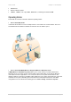
User’s Guide Chapter 4 – Reference Manual RADIUS Server AP2 AP1 IAPP Roaming Client Figure 27 – IAPP Roaming Scheme The wireless client is switched from AP1 to AP2 when entering the coverage area of the new access point (AP2). The roaming is performed without client re-authentication. The IAPP protocol ensures to inform the old AP1 of the new client association. The AP1 then stops the client RADIUS session, and the AP2 starts the client’s session with the RADIUS.
User’s Guide Chapter 4 – Reference Manual Figure 28 – Auto Channel Settings The auto-channel function is a great technique to minimize interference between access points. With auto-channel selection enabled the P-520r will regularly scan the air for neighboring access points and selects the channel with the least expected interference. The range of scanned channels can be limited by the administrator.
User’s Guide Chapter 4 – Reference Manual Configuration | Wireless | WDS Links The access point P-520r supports the definition of a WDS (Wireless Distribution System). In WDS mode a P-520r can act as wireless bridge or wireless repeater. Choose the Configuration | Wireless | WDS Links menu if you want to setup bridge links between different access points while connecting wireless client stations in parallel. Up to seven access points can be interconnected in a wireless distribution system.
User’s Guide Chapter 4 – Reference Manual SSID – displays the SSID of the access point. Data Rates – displays the transmit data rates of the remote access point. Channel – displays the channel that the access point uses to transmit and receive information. Age –indicates the age of the last information received from the remote access point in seconds. RSSI – shows the Received Signal Strength Indication (RSSI) of the access point. Cancel – restore all previous values. Apply – save changed configuration.
User’s Guide Chapter 4 – Reference Manual Figure 31 – Add WDS Link Manually OK – saves added new WDS Link in the WDS Links for internal radio table. Cancel – close the Add Wireless Distribution Link window without saving information. Follow the example to see how to configure a WDS. Case 1 – AP with WDS (Wireless Bridge). Create the wireless bridge between two wired networks: AP1 can be configured to forward all data to AP2 and vice versa.
User’s Guide Chapter 4 – Reference Manual Step 1 Choose the wireless MAC address of AP2 in the web configuration interface of AP1, menu WDS Links. Step 2 Choose the wireless MAC address of AP1 in the web configuration interface of AP2, menu WDS Links. Step 3 Select the same radio channel and the data rates for both APs using the Wireless Settings menu. Case 2 – AP with WDS (Wireless Repeater) This example shows a configuration where one AP relays all traffic wirelessly to another AP.
User’s Guide Chapter 4 – Reference Manual Configuration | Wireless | Advanced Settings For normal operation the following default settings do not need to be modified. Changing the P-520r advanced settings requires expert knowledge of the 802.11 protocol and the radio functionality.
User’s Guide Chapter 4 – Reference Manual Use the antenna diversity to select the best reception signal at the two integrated antennas. The main antenna is used for transmission whereas both antennas, primary and secondary, can receive signals. Receive diversity examines only packets directed at the AP. A count of frames received consecutively with FCS errors is compared to the configured threshold value. When this value is reached, the receive antenna used is switched to the other antenna.
User’s Guide Chapter 4 – Reference Manual Figure 34 – Access Control List (ACL) Settings You can further create your own access list if you need to define special access rules for specific network devices. The access control list is based on the network device's MAC address. In the access control table, you need only specify the network device MAC address and its access policy (accept/reject) with the new rule. Add – click to add ACL rule. Delete – click to remove selected ACL rule.
User’s Guide Chapter 4 – Reference Manual Access – select the permission of the rule to determine whether the specified network device shall be accepted or rejected by the access point. OK – saves added new ACL rule into configuration. Cancel – close the Add a Client window without saving information. Click the Delete button to remove desired ACL rule, and new pop-up window Delete Clients appears.
User’s Guide Chapter 4 – Reference Manual Figure 37 – RADIUS Servers' Settings Re-authentication Time – specify the number of seconds after which the access point reauthenticates client stations [0-2147483647]. The default value is 3600 seconds. If 0 is entered it means that stations will not have to re-authenticate as long as they are connected. IP address – displays RADIUS server’s IP address. Port Number – displays RADIUS server’s port number. Type – displays RADIUS server’s type.
User’s Guide Chapter 4 – Reference Manual IP Address – enter the RADIUS server IP address [digit and dots]. UDP Port – specify the network port used to communicate with RADIUS [1-65535]. Default: 1812. The port default value is 1812 in accordance with RFC 2865 " Remote Authentication Dial-in User Service (RADIUS)". Secret – specify the shared secret string that is used to encrypt data frames used for RADIUS servers [4-64 symbols]. Confirm Secret – re-enter the RADIUS secret to verify its accuracy.
User’s Guide Chapter 4 – Reference Manual Figure 40 – Wired Equivalent Privacy (WEP) Settings Enter the encryption key to be used to encrypt and decrypt wireless traffic: 64-bits – specify pre-shared key as 5 colon-separated HEX (0-9, A-F, and a-f) pairs (e.g. 00:AC:01:35:FF). 128-bits – specify pre-shared key as 13 colon-separated HEX (0-9, A-F, and a-f) pairs (e.g. 00:11:22:33:44:55:66:77:88:99:AA:BB:CC). Back – return to the main Wireless Security Settings page. Cancel – restore all previous values.
User’s Guide Chapter 4 – Reference Manual Figure 41 – 802.1X Security Settings Key Size and Group Rekeying unavailable when using WEP security. 64-bits – indicates that a 64-bit key is chosen for 802.1x security. 128-bits – indicates that a 128-bit key is chosen for 802.1x security. No rekeying – indicates that Group Key will not be changed dynamically. Rekey every … minutes – specify the time period in minutes, after which the group key will be updated [1-71582788]. Default value is 60 minutes.
User’s Guide Chapter 4 – Reference Manual The pre-shared key must match the one configured on your WLAN client stations. Back – return to the main Wireless Security Settings page. Cancel – restore all previous values. Apply – save changed configuration. WPA with RADIUS server makes use of external AAA (RADIUS) server to generate and exchange dynamic WPA keys between P-520r and the client stations.
User’s Guide Chapter 4 – Reference Manual Figure 44 – Change Administrator's Password New Password – specify new password value used for user authentication in the system [4-32 characters]. Confirm Password – re-enter the new password to verify its accuracy. Change Password – changes new specified administrator’s password. The password is also the SNMP Read-write community string. If the password is changed the SNMP community string will be changed as well.
User’s Guide Chapter 4 – Reference Manual Backup Configuration allows you to download the current system configuration and save to a file. Simply click the Backup button and specify the file location and name. Figure 47 – Download System Configuration File Backup – save the configuration as a file on your computer.
User’s Guide Chapter 4 – Reference Manual Use GMS System – select this checkbox to enable association of the device with GMS server. Setup connection to GMS server settings: Figure 51 – Connection to GMS server settings Use Persistent – select the checkbox to make a persistent connection to the GMS server.
User’s Guide Chapter 4 – Reference Manual Password – specify the password for certificate PKCS12 file [string]. Only used if the certificate key is encrypted. Identifier – specify the unique identifier used for client authentication [all ASCI characters].
User’s Guide Chapter 4 – Reference Manual Specify the alarms settings: Figure 54 – Specify the Alarm Settings Use Alarms – select the checkbox if need to enable the alarm gathering. Level – specify the message level [emergency/alert/critical/error/warning/notice/info/debug]. Messages that have this level or any level of greater importance are considered alarms and are reported to the RCMS agent. Default – errors.
User’s Guide Chapter 4 – Reference Manual Cancel – close the Add OID window without saving information. Use the SNMP agent to discover what OIDs are implemented on P-520r and can be monitored on the GMS server. Configuration | System | SNMP Traps SNMP is another management interface for the P-520r. In particular it provides the ability to send trap messages with notifications or alarms to a management system. You can configure the SNMP agent in P-520r to send SNMP traps to one or more SNMP managers.
User’s Guide Chapter 4 – Reference Manual Figure 59 – Delete Trap Host IP OK – removes selected SNMP manager IP addresses from the system. Cancel – close the window without saving information. Configuration | System | NTP Settings The NTP (Network Time Protocol) is used to synchronize the clock of the access point to a selected time reference.
User’s Guide Chapter 4 – Reference Manual NTP Server – displays the NTP server. Cancel – click the button to cancel changes. Apply – click the button to save auto time and date settings. To add the NTP host, click Add button under the NTP server’s table and a new pop-up window Add NTP Server appears: Figure 61 – Add a New NTP Server NTP Server – specify the trusted NTP server host [1-128]. OK – saves added NTP host into configuration. Cancel – close the window without saving information.
User’s Guide Chapter 4 – Reference Manual Figure 62 – Delete a NTP server OK – removes selected NTP host from the system. Cancel – close the window without saving information. Configuration | System | Automatic Reboot The Automatic Reboot feature allows to reboot the P-520r device automatically at the scheduled time. Figure 63 – Automatic Reboot Configuration Enable Automatic Reboot – select this option if you want to activate Automatic Reboot function and specify settings.
User’s Guide Chapter 4 – Reference Manual Status Status | Statistics/Usage | Status Overview Use the Status | Statistics/Usage | Status Overview menu for a summary of status information of your access point. Figure 64 – Status Overview Uptime – indicates the time, expressed in hours, minutes and seconds since last reboot [hours:minutes:seconds]. Wireless Clients – indicates the total number of currently connected client stations.
User’s Guide Chapter 4 – Reference Manual Figure 65 – Interface Statistics Interface – indicates a unique name for each interface. Status – shows the current operational state of the interface [up/down]. InOctets – indicates the amount of received bytes on the interface, including framing characters. InUcast – totals unicast frames received at the port excluding discards. InMcast – totals multicast frames received at the port excluding discards.
User’s Guide Chapter 4 – Reference Manual RTS Success Count – displays the total of successfully received RTS packets. RTS Failure Count – displays total of not received RTS packets. ACK Failure Count – displays total of expected but not received ACK (acknowledgement) frames. Received Fragment Count – displays total of each successfully received MPDU (MAC Protocol Data Unit) of type Data or Management.
User’s Guide Chapter 4 – Reference Manual Facility – indicates the unique identifier of the facility that generated the event. A facility can be a hardware device, a protocol, or a module of the system software. [Kernel/User/Security/Clock/LogAudit/LogAlert/System/Network/Wlan/management] ID – indicates an internal number for the event. Description – indicates description of the event. Count – indicates the number of times this event has occurred.
User’s Guide Chapter 4 – Reference Manual Figure 69 – Detected Access Points with Internal Radio BSSID – displays the MAC address of the remote access point. SSID – displays the network name (SSID) of the remote access point. Data Rates – displays the range of data transmission rates supported by a device in megabits per second (Mbps). Channel – displays the channel of the remote access point. Age – shows the age in seconds of the last information received from the remote AP.
User’s Guide Chapter 4 – Reference Manual Update We recommend to regularly check for new Software updates on the Gemtek Systems website: http://www.gemtek-systems.com To update your device firmware, use only the original Gemtek System firmware image and click the update button on main menu. New Update Wizard pop-up window appears. Figure 71 – Update Wizard Next – click to continue the firmware update process. Cancel – click to cancel the firmware update process.
User’s Guide Chapter 4 – Reference Manual Figure 72 – New Firmware Upload Browse – click the button to specify the new image location. Update – upload with new firmware. Cancel – cancel the upload process. Back – return to main firmware update wizard page. New firmware image is uploaded and system firmware update begins. New window with informational message and remaining time appears.
User’s Guide Chapter 5 – SNMP Management Chapter 5 – SNMP Management Introduction Another way to configure and monitor the access point (P-520r) via a TCP/IP network is SNMP (Simple Network Management Protocol). SNMP is an application layer protocol that facilitates the exchange of management information between network devices. It is part of the Transmission Control Protocol/Internet Protocol (TCP/IP) protocol suite.
User’s Guide Chapter 5 – SNMP Management authenticationFailure An authenticationFailure trap signifies that the SNMP entity, acting in an agent role, has received a protocol message that is not properly authenticated. linkDown A linkDown trap signifies that the SNMP entity, acting in an agent role, recognizes a failure in one of the communication links represented in the agent's configuration.
User’s Guide Chapter 5 – SNMP Management P-520r get-request, get-next-reguest, get-bulk, set-request get-response, traps MIB SNMP Agent SNMP Manager Figure 74 – SNMP Network Gemtek Systems Private MIB In addition to standard SNMP MIBs the P-520r supports the private Gemtek Stystems MIB. The private MIBs are enterprise specific and serve to extend the functionality of the standard MIBs. Private MIB identifies manageable objects and their properties that are specific to the managed device.
User’s Guide Appendix Appendix A) P-520r Operator Access Point Specification Technical Data Features Theft protection system IEEE 802.11g/b Access Point, Wi-Fi compliant WPA (PSK, TKIP, Rekeying)/WEP support Integrated high-gain diversity antennas 802.
User’s Guide Appendix Dimension 196mm x 142mm x 35 mm/ 7.6 x 5.5 x 1.4 (L x W x D) Weight 350g / 0.771 lbs Environment Specification Temperature 0°C to 45°C Humidity 10% to 95%, non-condensing Power Supply Power Adaptor External AC/DC converter 100/230V to 5V DC/1.5A, 4.2W max. Optional Power Supply Power-over-Ethernet IEEE 802.
User’s Guide Appendix B) Factory Defaults Values for the P-520r Access Point The following settings and parameters are the factory default for the 54Mb Operator Access Point model: P-520r. Configuration: Identity Name name Location location Contact contact information Local Area Network: Network Setup Dynamic IP Selected Static IP Not Selected Virtual LAN Use Virtual Local Network (VLAN) Not selected VLAN id none Wireless Basic Wireless Settings Broadcast SSID Selected PRISM Nitro.
User’s Guide Appendix Wireless Security | RADIUS Servers Reauthentication Time 3600 No RADIUS servers are defined on the system in the default status Wireless Security | Wired Equivalency Privacy (WEP) Use WEP Security Not selected Wireless Security | 802.1X Security 802.
User’s Guide Appendix C) P-520r Rescue and Firmware Recovery via TFTP Booting P-520r in rescue mode: 1. Turn off power on P-520r. 2. Push reset button (see on Figure 4 – Looking Inside the P-520r) when booting on P-520r. 3. Wait 3 seconds, release button. P-520r boots on rescue mode therefore will get IP address from DHCP. Upload firmware (FW update) to P-520r via TFTP: $ tftp tftp> bin tftp> put Sent 1377280 bytes in 51.
User’s Guide Glossary Glossary D Symbols: Datagram Self-contained, independent entity 10BASET 10 Mbps/baseband/twisted pair. of data carrying sufficient information to be routed from the source to the destination computer without reliance on earlier exchanges between this source and destination computer and the transporting network.
User’s Guide Glossary F I filter A device that selectively sorts signals and ICMP Internet Control Message Protocol. The passes through a desired range of signals while suppressing the others. This kind of filter is used to suppress noise or to separate signals into bandwidth channels. TCP/IP protocol used to handle errors and control messages at the IP layer. ICMP is part of the IP protocol.
User’s Guide Glossary M P MAC (Media Access Control) The unique hardware number of a device connected to a shared media. On an Ethernet it is the same interface as the Ethernet address. packet The unit of data sent across a network. metric A concept used to describe the cost of a route across a network, the distance to the destination at the remote end of the route, or the capacity of the route.
User’s Guide PPPoE: PPPoE (Point-to-Point Protocol over Ethernet) is a specification for connecting multiple computer users on an Ethernet local area network to a remote site through common customer premises equipment, which is the telephone company's term for a modem and similar devices. PPPoE can be used to have an office or building-full of users share a common Digital Subscriber Line (DSL), cable modem, or wireless connection to the Internet.
User’s Guide Glossary Router On the Internet, a router is a device or, topology A network topology shows the in some cases, software in a computer, that determines the next network point to which a packet should be forwarded toward its destination. The router is connected to at least two networks and decides which way to send each information packet based on its current understanding of the state of the networks it is connected to. computers and the links between them.
User’s Guide Index Index A Access Point with WDS wireless bridge, 10, 11 wireless repeater, 12 Access your AP, 20 ACL, 47 Advanced Wireless Settings, 46 Antenna Gain, 41 AP mode, 10 auto-channel, 41 automatic reboot, 63 B Backup/Restore, 55 Basic rate, 46 Basic Wireless Settings, 39 Beacon period, 46 C Cable inlet, 16, 17 Configuration, 84 D Default, 49 Defaults, 16, 40, 47 configuration, 77 LAN, 77 security, 77 wireless, 77 DHCP, 38, 84 Domain, 84 download system configuration, 56 E Ethernet Socket,
User’s Guide PRISM Nitro, 41 Product overview, 8 Q QOS, 87 R Index access points, 67 event reporting, 66 interface statistics, 64 wireless clients, 67 wireless statistics, 65 support, 7 Supported rate, 46 System requirements, 13 Radio channel, 40 RADIUS, 87 RADIUS server, 54 RADIUS servers, 49 Reboot, 56 Regulatory Domain/Channels, 74, 76 Reset, 16 using hardware, 23 using KickStart, 23 using software, 56 Restore configuration, 55 RTS threshold, 46 T S VLAN, 38 Security, 29 802.