BW1251 Dual Radio 2.4GHz/5GHz Access Point www.browan.com User’s Guide V1.
Copyright © 2002-2006 BROWAN COMMUNICATIONS This product plan and the software described in it are copyrighted with all rights reserved. No part of this publication may be reproduced, transmitted, transcribed, stored in a retrieval system, or translated into any language in any form by any means without the written permission of BROWAN COMMUNICATIONS. Notice BROWAN COMMUNICATIONS reserves the right to change specifications without prior notice.
Within the band between 5.15 and 5.25 GHz (5GHz radio channels 34 to 48) the UNII devices are restricted to indoor operations to reduce any potential harmful interference to MSS operations. FCC Warning FCC Interference Statement This equipment has been tested and found to comply with the limits for a Class B digital device, pursuant to Part 15 of the FCC Rules. These limits are designed to provide reasonable protection against harmful interference in a residential installation.
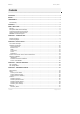
BW1251 Nov 15, 2006 Contents COPYRIGHT........................................................................................................................................... 1 NOTICE................................................................................................................................................... 1 TRADEMARKS....................................................................................................................................... 1 FCC Warning...............
BW1251 Nov 15, 2006 Wireless | Advance ........................................................................................................................46 Wireless | WEP ..............................................................................................................................54 Wireless | MAC ACL ......................................................................................................................55 System..........................................................
BW1251 Nov 15, 2006 About this Guide Purpose This document provides information and procedures on hardware installation, setup, configuration, and management of the BROWAN high performance Dual Radio 2.4GHz/5GHz AP BW1251. Prerequisite Skills and Knowledge To use this document effectively, you should have a working knowledge of Local Area Networking (LAN) concepts and wireless Internet access infrastructures.
BW1251 Nov 15, 2006 Chapter 1 – Introduction Thank you for choosing the BROWAN Dual Radio Access Point BW1251. The BROWAN BW1251 operates simultaneously in both 5 GHz and 2.4 GHz frequency bands and is fully compliant to 802.11b/g and 802.11a standard with its high performance and enhanced security. The two Dual-Band radio (a/g + a/g) feature supplies the furthest in flexibility and makes sure low interference and large coverage.
BW1251 Nov 15, 2006 Multiple BSSID Support up to 16 BSSID per radio and each can be configured independently to support different range of security policy, authentication methods, RADIUS servers and VLAN IDs. Each BSSID can be set by its priority on a basis of 802.1p tag or 802.11e EDCA which enables WLAN client device to access wireless link QoS capabilities. Simple Installation Support IEEE 802.3af Power-over-Ethernet as well as external power supply by power adaptor.
BW1251 Nov 15, 2006 Accounting supporting (RFC 2866) Security Static 64/128bits WEP, Dynamic 64/128bits WEP WPA/TKIP and WPA/AES support MAC ACL Access Control (accept rule and deny rule) based on MAC address Layer 2 Isolation Hidden SSID Management Secure management via HTTPS, CLISH, SNMP Standard MIB and BROWAN Private MIB BROWAN NMS Support Detail Client Survey Network interface statistics Remote firmware update via WEB UI Backup/Restore configuration file DHCP S
BW1251 Nov 15, 2006 Chapter 2 - Installation This chapter provides installation instructions for the hardware and software components of the Access Point BW1251. It also includes the procedures for the following tasks: Hardware Introduction (LEDs, Connectors) Connecting the Access Point Software Installation The Product Package The product deliverables: BW1251 Dual Radio 2.
BW1251 Nov 15, 2006 Hardware Introduction General Overview Figure 1 – BW1251 General View The front panel of BW1251 contains: There are 4 indicator lights (LEDs) that help to describe the state of various networking and connection operations.
BW1251 Nov 15, 2006 Bottom Cover Figure 2 –Bottom Cover of the BW1251 The Bottom Cover of the BW1251 contains: 1. Back Label with Model and Device name. The official device name is Dual Radio 2.4GHz/5GHz Access Point, model BW1251. 2. Serial Number label of the device. 3. MAC address label of the device. The MAC label shows the WLAN1 interface MAC address of the device.
BW1251 Nov 15, 2006 Item LED Color 1 Green Power 2 LAN 3 Wireless1 Green Green (802.11g module is functional) Amber (802.11a module is functional) 4 Wireless2 Green (802.11g module is functional) Amber (802.
BW1251 Nov 15, 2006 Stand The BW1251 is designed to stand alone. Refer to the direction of red arrow to release and insert the stand on the back of BW1251. Figure 5 – release stand Figure 6 – insert stand Wall Mount BW1251 is also designed for wall mounting. Refer to the step 1 and step 2 to fix the stand on the wall and lock the BW1251 on it.
BW1251 Nov 15, 2006 Connect to the Power Source and Local Network BW1251 can be powered on by connecting to either one of the following two devices: ♦ Power-over-Ethernet ♦ External Power Adapter Case 1 Use the Power-over-Ethernet: Use the enclosed power cord and any IEEE802.3af Compliant POE Power Source Devices to supply power to your BW1251 Access Point. Step 1 Place the Access Point on a flat work surface or mount it on the wall.
BW1251 Nov 15, 2006 The default network settings for your new access point are: LAN port: IP 192.168.2.2 subnet 255.255.255.0 Software Introduction: KickStart The BROWAN KickStart is a software utility included on the Installation CD. The utility automatically detects access points or access controllers installed on your network regardless of its host IP address and lets you configure each unit’s IP settings.
BW1251 Step 3 Nov 15, 2006 After successfully logging on, you will see the main page of the BW1251’s Web user interface: If second method is prefered, please follow the instructions: Step 1 Browan Install the KickStart utility from the product CD. Click Start > Programs > BROWAN > KickStart to launch the application.
BW1251 Step 2 Browan Nov 15, 2006 Select your controller and right click.
BW1251 Step 3 Nov 15, 2006 Enter the BW1251 administrator login credential to access the web management interface. The default administrator log on settings for all access point interfaces are: User name: admin Password: admin01 Step 4 Browan After successfully logging on, you will see the web interface.
BW1251 Nov 15, 2006 Chapter 3 – Application Mode The two Dual-Band radios (a/g + a/g) supply the furthest flexible application. Three application modes are supplied by BW1251: z AP + AP mode z AP + Bridge mode AP + AP Mode AP + AP configuration can be for client density environment. The typical recommended usage is: 11g AP + 11a AP. Figure 9 – AP +AP application mode AP + Bridge Mode AP + Bridge configuration is for environment with last mile issue.
BW1251 Nov 15, 2006 Figure 10 – AP +Bridge application mode Because of the antenna interference, the performance will deteriorate dramatically if the same band (2.4GHz or 5GHz) is used on both RF modules. It is strongly recommended that one RF module uses 2.4GHz and the other uses 5GHz.
BW1251 Nov 15, 2006 Chapter 4 – Reference Manual This chapter contains web management reference information.
BW1251 Nov 15, 2006 Reset – rebooting device and restoring systems to the factory default Upgrade – Upgrading the firmware remotely In the following sections, short references for all menu items are presented. Status Status | Device Status The device status page shows important information of the BW1251, its system status and network configuration.
BW1251 Nov 15, 2006 VLAN – specifying whether to manage this device via VLAN. VLAN ID – specifying VLAN ID when managing this device via VLAN. Status | Wireless Status The wireless status shows the information related to BW1251’s two wireless interfaces. 2 19 dBm 2 dBi 18 dBm Figure 13 – Wireless Status Radio1 / Radio2 – the wireless interfaces of the BW1251 Channel – indicating the channel in use.
格式化: 字型: (中文) 新 細明體, (中文) 中文 (台 灣) BW1251 Nov 15, 2006 Status | Interface Statistics The Interface Statistics shows each network interface status, including Input / Output bytes, packets or error. Figure 14 – Interface Statistics Interface Name – showing the name of each network interface, where ixp0 is related to LAN interface, wlan1_x is related to WLAN1 sub-interface and wlan2_x is related to WLAN2 sub-interface. Input Bytes (KB) – showing the total number of bytes received on the network interface.
BW1251 Nov 15, 2006 Network Network | Interface The interface configured is bridge device, therefore only one interface is displayed here for configuration. Bridge interface and its settings are listed on the Interface page. Figure 15 – Interface Configuration Table To change network interface (bridge) configuration properties, click the Edit button in the Action column.
BW1251 Nov 15, 2006 Figure 57 – Apply or Discard Interface Configuration Changes Apply Changes – saving all changes in the interface table at once. Discard Changes – restoring all previous values. Every time the settings are changed, the BW1251 needs to be restarted to apply all settings changes when clicking Apply Changes. Request for server reboot appears: Figure 18 – Reboot Server Reboot – restarting the server and applying the changes.
BW1251 Nov 15, 2006 Figure 19 – Reboot Information Network | RADIUS Server Up to 32 different RADIUS servers can be configured under the RADIUS servers menu. By default, one RADIUS server is specified for the system: Figure 20 – RADIUS Servers Settings Add – adding a new RADIUS server. Click Add to configure RADIUS server settings.
BW1251 Nov 15, 2006 Name – specifying the new RADIUS server name used for selecting RADIUS server. Server IP – authentication RADIUS server IP address [dots and digits]. Server Port – specifying the network port used to communicate with RADIUS [1-65535]. The default port value for authentication is 1812. The default port value for accounting is 1813. The port specified here must be the same with the one on the RADIUS server.
BW1251 Nov 15, 2006 If there is no other setting needed to be modified, click the Reboot button to apply all modifications. And if there are still other setting modifications needed, go ahead to finish all changes and then click Reboot button to restart and apply all settings together. Network | DHCP Settings BW1251 can act as DHCP server or DHCP relay. The DHCP (Dynamic Host Configuration Protocol) service is supported on layer 2 interfaces. DHCP server and DHCP relay are disabled by default.
BW1251 Nov 15, 2006 Figure 116 – DHCP server Settings By default, DHCP server is disabled for BW1251. IP Address from / IP Address to – specifying the IP address range to be dynamically allocated by the DHCP server. Netmask – the netmask for IP pool range. Gateway – the gateway IP for wireless clients. WINS Address (Windows Internet Naming Service) – specifying the server IP address if it is available on the network [dots and digits].
BW1251 Nov 15, 2006 Figure 127 – Apply or Discard DHCP server Settings The DHCP server settings will be automatically adjusted to match the network interface settings. The Gateway of DHCP server settings must be same with the Gateway of BW1251 Every time settings are changed, the BW1251 needs to be restarted to apply all settings changes when clicking Apply Changes.
BW1251 Nov 15, 2006 Figure 138 – Reboot information Reboot – restarting the server and applying the changes. If there is no other setting needed to be modified, click the Reboot button to apply all modifications. And if there are still other setting modifications needed, go ahead to finish all changes and then click Reboot button to restart and apply all settings together. When BW1251 network Interface uses DHCP to get IP address dynamically, DHCP server service cannot be enabled.
BW1251 Nov 15, 2006 Figure 30 – DHCP Relay settings Server IP – the IP address of the external DHCP server. Only one DHCP server can be supported for DHCP relay feature. Change status or leave the default state if no editing is necessary and click the Save button. Figure 31 –Apply or Discard DHCP relay Settings Every time settings are changed, the BW1251 needs to be restarted to apply all settings changes when clicking Apply Changes.
BW1251 Nov 15, 2006 When BW1251 network interface uses DHCP to get IP address dynamically, DHCP relay service cannot be enabled. Network | NTP Settings NTP (Network Time Protocol) is used to synchronize the system time with the selected network NTP server. Use the Network| NTP Settings menu to configure the NTP service: Figure 153 – NTP Settings NTP Status – enabling or disabling NTP service. Time Zone – specifying the time zone for NTP service. Delete – deleting the existed NTP server.
BW1251 Nov 15, 2006 Change status or leave the default state if no editing is necessary and click the Save button. Figure 175 – Apply or Discard NTP server Changes Choose the Time Zone for your local area time and enable or disable the NTP status Figure 18 – Edit Time Zone setting/NTP status Click the Save button to save new Time Zone setting.
BW1251 Nov 15, 2006 BW1251 needs to be rebooted to save all configurations. After clicking Apply Changes, request for server reboot appears as shown below: Figure 208 – Reboot information Reboot – restarting the server and saving the configuration edited If there is no other setting to be edited, click the Reboot button to save all configurations.
BW1251 Nov 15, 2006 Change the Date and Time or leave the default value if no editing is necessary and click the Apply button. Thus the modified time will be taken effect at once. No reboot is needed. If NTP is enabled, the local time cannot be modified. Since BW1251 hasn’t RTC (real-time clock), the system time will show 1970/01/01 00:00 every time the device reboots.
BW1251 Nov 15, 2006 19 Figure 42 – Basic Wireless Settings with DCA enabled Radio – specifying which wireless interface of BW1251 is shown. Domain – showing the regulatory domain. Static Channel / Auto Channel – showing the channel that the access point will use to transmit and receive information. If DCA (Dynamic Channel Allocation) is enabled, this will show Auto Channel and its channel number is chosen by auto channel selection.
BW1251 Nov 15, 2006 DCA optional channel – showing the channels only in which auto channel selection (DCA) will be processed to reduce interference. Only when DCA is enabled, DCA threshold and DCA optional channel will be shown. Layer 2 Isolation – showing the status of Layer 2 Isolation service (enabled or disabled) Mode – showing the mode that the Access Point is in.
BW1251 Nov 15, 2006 Figure 44 – Site Survey information To refresh the statistics click the Rescan button. During Site Survey, all wireless clients connected to the BW1251 would be kicked off. Site Survey takes some minutes to perform. Please wait and don’t power off AP during site survey. Edit – editing the wireless basic settings To change basic wireless setting properties, click the Edit button in the Action column.
BW1251 Nov 15, 2006 19 Figure 45 – Edit Basic Wireless Settings with static channel selection 19 Figure 46 – Edit Basic Wireless Settings with DCA enabled Browan Page 41 of 72
BW1251 Nov 15, 2006 Radio Name – specifying the wireless interface of the BW1251 Domain – selecting the regulatory domain according to your country The full frequency range between 2.4 GHz and 5 GHz is not permitted for use in all countries. Depending on your selection of regulatory domains, the available frequency channels will vary. Before changing radio settings manually, make sure that your settings comply with the government regulations.
BW1251 Nov 15, 2006 Security Policy Disable C) Regulatory Domain/Channels. Channels – selecting the channel that the access point will use to transmit and receive information. If one channel is defined, it acts as the default channel. Channels list will vary depending on selected regulatory domain and selected band. Multiple frequency channels are used to avoid interference between two radios of this AP, and between nearby access points.
BW1251 Nov 15, 2006 If wireless network environment is stable, which means auto channel selection isn’t needed frequently, set a big value for DCA threshold to gain a stable wireless users’ connection. If wireless network environment changes continually, frequent auto channel selection is needed, set a relatively small value for DCA threshold to let channel change based on wireless environment.
BW1251 Nov 15, 2006 19 dBm 2 dBi Figure 48 – Apply or Discard Basic Wireless Settings with DCA enabled Every time settings are changed, the BW1251 needs to be restarted to apply all settings changes when clicking Apply Changes. Request for server reboot appears: 19 dBm 2 dBi Figure 49 – Reboot Server Reboot – restarting the server and applying the changes. If there is no other setting to be edited, click the Reboot button to save all configurations.
BW1251 Nov 15, 2006 Wireless | Advance BW1251 supports Multiple BSSID (MBSSID) function. You can configure up to 16 BSSIDs per radio on BW1251 and assign different configuration settings to each BSSID. For wireless users, they can think BW1251 as a single AP with multi services supported, including different security policy, different VLAN ID, different authentication etc.
BW1251 Nov 15, 2006 Figure 51 – Detail for MBSSID entry Radio – showing which radio (WLAN1 or WLAN2) is displayed Interface – showing the sub-interface of specified Radio Mode – Showing the operation mode of the sub-interface SSID – Showing the SSID value of the sub-interface Hidden SSID – Showing the enabled/disabled status of Hidden SSID service Use VLAN – Showing if VLAN is used for the sub-interface VLAN ID – showing the VLAN ID specified when VLAN is used 802.1p Tag – Showing the 802.
BW1251 Nov 15, 2006 Figure 52 – Detail information of connected client Client MAC – showing the connected client’s MAC address IP Addr – showing the IP address of the connected client Auth Type – showing the security policy that the connected client uses Signal/Noise – showing the SNR value of the connected client Input Packets – showing the number of packets transmitted by the connected client Output Packets – showing the number of packets destined to the connected client Clicking New or Edit on AP mod
BW1251 Nov 15, 2006 Hidden SSID – when enabled, the SSID of this Interface is invisible in the networks list while scanning the available networks for wireless client (SSID is not broadcasted with its Beacons). When disabled, the AP’s SSID is visible in the available networks list [enabled/disabled]. By default, the Hidden SSID is disabled. VLAN and QoS – specifying VLAN policy or QoS policy. Data priority is based on (B) SSID and is implemented by 802.11e EDCA or 802.1p tag.
BW1251 Nov 15, 2006 Figure 54 – Multiple BSSID Setting – 2 Security – specifying the security policy. WEP – when selected, the privacy of MSSID entry will be set to WEP (Wired Equivalent Privacy). WEP Key Index – selecting the default key Index to make it the Default key and encrypt the data before being transmitted. All stations, including this MSSID Entry, always transmit data encrypted using this Default Key. The key number (1, 2, 3, 4) is also transmitted.
BW1251 Nov 15, 2006 Figure 55 – Multiple BSSID Setting – 3 WPA-PSK – when selected, the encrypt method will be WPA without RADIUS server. WPA2-PSK – when selected, the security policy will be WPA2 PSK without RADIUS server. In this mode, only WPA2 PSK client can connect with AP and WPA PSK client is not permitted to connect. WPA2-PSK MIXED – when selected, WPA2 PSK and WPA PSK are all permitted to connect with AP.
BW1251 Nov 15, 2006 Bridge Mode Figure 56 – Advanced Wireless Setting (Bridge Mode) Radio – specifying which RF card (wlan1 or wlan2) is needed to be configured since BW1251 has two Dual-Band radios Mode – specifying the operation mode of BW1251 (AP or Bridge) Interface – choosing the specified Bridge link entry you want to configure.
BW1251 Nov 15, 2006 Figure 58 – Bridge Link Setting Remote MAC – adding a remote peer’s MAC address you want to configure as a bridge link Security – specifying WEP or WPA-PSK (TKIP or AES) used for security policy. WPA-PSK or static WEP can be used for encrypt each bridge link Each Bridge link can have its own WEP key/key Index for encryption. By default, four WEP keys are all set to “6161616161”. They can be modified in Wireless | WEP.
BW1251 Nov 15, 2006 Wireless | WEP Use the Wireless | WEP menu to configure static WEP settings. This menu only sets static WEP key value related with 4 key indexes for each RF card (wlan1 or wlan2). Enabling or Disabling static WEP is in the Wireless | Advance menu. Figure 59 – WEP Settings Radio – specifying which RF card (wlan1 or wlan2) is needed to be set. Click Edit to edit the existing wepkey1 to wepkey4. By default, four WEP keys are all set to “6161616161”.
BW1251 Nov 15, 2006 Wireless | MAC ACL Use the MAC ACL service to control the default access to the wireless interface of the BW1251 or define special access rules for mobile clients. Configure the ACL using the Wireless | MAC ACL menu: Figure 61 – MAC ACL Service Radio – two wireless interfaces wlan1 and wlan2 can be selected for each radio’s MAC ACL rules. Only AP mode has the MAC ACL service. MAC ACL service.is not available for Bridge mode.
BW1251 Nov 15, 2006 You must create MAC List to work with Policy setting. The access control list is based on the network device’s MAC address. In the MAC ACL Configuration table, you only need to specify the MAC address of wireless client. Click the Add button to create a new MAC entry: Figure 63 – Add MAC entry MAC Address – the physical address of the network device (MAC address) you need to configure. The format is a list of colon separated hexadecimal numbers (for example: 00:AA:A2:5C:89:56).
BW1251 Nov 15, 2006 Figure 65 – Reboot Server Reboot – restarting the server and applying the changes. If there is no other setting to be edited, click the Reboot button to save all configurations.
BW1251 Nov 15, 2006 System System | Security Use the System | Security service to configure the name and password of administrator: Figure 66 – system security settings User Name – administrator username for access to BW1251 (e.g. web interface, CLI mode) [1-32 symbols, spaces not allowed]. Old Password – old password value. New Password – new password value used for user authentication in the system [4-8 characters, spaces are not allowed].
BW1251 Nov 15, 2006 Figure 67 – system security settings save and take effect successfully System | SNMP SNMP is the standard protocol that regulates network management over the Internet. To communicate with SNMP manager you must set up the same SNMP communities and identifiers on both ends: manager and agent. Use the System | SNMP menu to change current SNMP configuration. Figure 68 – SNMP settings Readonly community – community name is used in SNMP version 1 and version 2c.
BW1251 Nov 15, 2006 You can configure your SNMP agent to send SNMP Traps (and/or inform notifications) under the defined host (SNMP manager) and community name (optional). Figure 69 – SNMP Trap table settings Click Add to add a new SNMP manager or Delete to delete a specific SNMP manager. Clicking Add: Figure 70 – Add SNMP Trap Host IP – entering the SNMP manager’s IP address [dots and digits]. Host Port – entering the port number the trap messages should be send through [number].
BW1251 Nov 15, 2006 Backup – downloading current working system configuration for backup Upload/Restore – uploading system configuration to restore Figure 72 – System Configuration settings You can save your current device configuration file locally using the Backup menu under the System | Configuration | Backup menu: Figure 73 – Backup settings Such device configuration is saved in the specific format file (.cfg). Description Message shows the current version of firmware.
BW1251 Nov 15, 2006 Figure 75 – Configuration Upload/Restore Click Upload to upload the specified configuration file and then the UI below appears Figure 76 – configuration information HOST IP – showing the IP address in the configuration file that needs to be uploaded. Please remember this IP address for accessing BW1251 after the configuration file is uploaded. HOST VERSION – showing the firmware version in the configuration file that needs to be upload.
BW1251 Nov 15, 2006 Figure 77 – System Reset setting Reboot – rebooting the device Reset – resetting the System to the Factory Defaults To reboot the device, click Reboot and then the confirming message below appears: Figure 78 – Reboot the device To reset device to the factory defaults, click Reset on Figure 77 – System Reset setting and then the below appears to confirm: Figure 79 – Reset the device Please note that all settings including the administrator settings will be set back to the factory
BW1251 Nov 15, 2006 Click the Upload, and then the following will appear. Specify the full path to the new firmware image and click the Upload button: Figure 81 – Firmware Upgrade To flash the uploaded firmware image to upgrade the firmware is done by clicking the Upgrade button. Please make sure the firmware is correct for BW1251. Otherwise the upgrade will be failed.
BW1251 Nov 15, 2006 Appendix A) Specification Wireless Standard IEEE 802.11b(DSSS), IEEE 802.11g(OFDM) and IEEE 802.11a(OFDM) Data Rate 802.11a: 54,48,36,24,18,12,9,6Mbps;802.11g: 54,48,36,24,12,9,6,11,5,5,2,1Mbps (auto fall back) Transmit Power (adjustable RF power) Max. 19 dBm ± 1.5dBm @ 2.4GHz Max. 18 dBm ± 1.
BW1251 Nov 15, 2006 Related Products Controllers: BE9040 SMB Access Controller Access Points: BW2250 54Mb Dual-bang outdoor Access Point Browan Page 66 of 72
BW1251 Nov 15, 2006 B) Factory Defaults for the BW1251 General Configuration Settings Administrator Username Administrator Password Get Community Set Community admin admin01 Public Private Network Configuration Settings IP address Subnet mask Gateway (static IP) 192.168.2.2 255.255.255.0 0.0.0.
BW1250 Sep.
BW1250 Sep.
BW1250 Sep. 22, 2006 D) Location ID and ISO Country Codes This list states the country names (official short names in English) in alphabetical order as given in ISO 3166-1 and the corresponding ISO 3166-1-alpha-2 code elements. It lists 239 official short names and code elements.
BW1250 Sep.
BW1250 Sep.
BW1250 Sep.
BW1251 Nov 15, 2006 E) Antenna Specification Browan Page 73 of 72