
User Manual

Form 261
Bulletin P/N 100204-1
Rev. K
This bulletin should be used by experienced personnel as a guide to the installation of the Series 26M Control. Selection
or installation of equipment should always be accompanied by competent technical assistance. We encourage you to
contact Gems Sensors or a representative if further information is required.
Installation
1. Install octal socket in appropriate enclosure
using two #6 or #8 screws.
2. Install rail mount socket on appropriate rail
(DIN mount) in appropriate enclosure if appli-
cable.
3. Wire control per wiring diagram following
N.E.C and local codes.
4. Install control module in socket.
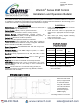
Warrick
®
Series 26M Control
Installation and Operation Bulletin
Specifications
Control Design:
Solid-state components enclosed in a clear Lexan
plug-in style housing. Not NEMA rated.
Contact Design:
1 SPDT (1 form C), powered contacts
(input Power L1 connected to common of relay contacts)
Contact Ratings:
10A@120/240-VAC resistive (120°F), 1A
@120/240VAC resistive (150°F), 1/3 HP @ 120/240-VAC (120°F).
Contact Life:
Mechanical -5 million operations
Electrical -100,000 operations minimum at rated load
Supply Voltage:
Factory Configured: 24V, 120V, 220V, or 240V AC
+10%/-15% of nominal, 50/60 Hz. Factory Configured: 208V/240V
Model: 187V Min to 242V Max, VAC 50/60 Hz
Power Consumption:
24/120/220/240-VAC with both relays ener-
gized
~
4.4 VA.
Secondary Circuit:
2.3 VAC RMS voltage on probes, < 1 milliam-
pere source capability.
Sensitivity:
Factory programmed to 4.7K, 10K, 26K, 50K, or 100K
Ohms
Operating Ambient Temperature Range:
-40°F to +150°F
(
-40°C to
+65°C)
Terminals:
All connections made with screw-clamp terminals.
Time Delays:
Standard LLCO, 0.5 sec. on rising level, 3 sec. on fall-
ing level. Optional 0-90 sec. time delays in 1-sec. increments for
rising and falling.
Listings:
Control carries U.L. Limit Control Listing (UL-353) for
24VAC and 120VAC Line Powered units only (220VAC, 240VAC,
208/240VAC units not rated).
SENSITIVITY
CHARACTER
SENSITIVITY
(K-OHMS)
Distance
(FT)
A 4.7 900
B 10 600
C 26 250
D 50 100
E 100 50
∗ Based on type MTW or THHN wire,
#14 or #16 AWG
Sensitivity vs. Maximum
Probe Wire Distance*
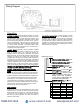
Dimensional Drawing
Torque all terminals and socket mounting screws to 7 in-lb max.
Mount the octal socket
(base) on rigid vertical
or horizontal surface
using #6 or #8 screws.
The control should be
mounted within an
enclosure of proper
NEMA integrity.
www.calcert.com sales@calcert.com1.888.610.7664
0
5
10
15
20
25
30