
User Manual

560550-0128 Issue A Page 2 of 4
* The pressure transducer has no means of draining or venting, this must be performed by
another component in the end users system.
* Pressure range must be compatible with the maximum pressure being measured.
* Pressure media must be compatible with the transducer/transmitter wetted parts listed in
these instructions.
* Liquid must not be allowed to freeze in the pressure port.
* The gasket must be fitted under the electrical connector (mini-din only).
* Supply voltage must not exceed the value stated on the unit label.
MECHANICAL INSTALLATION
Mounting: Pressure Transducer is designed to be attached by the coupling thread only. Omni-
directional, self supported directly into the pipework. Use a 22mm spanner on the hexagon
provided to apply a maximum torque of 15Nm. The Customer must ensure that the pressure seal
is suitable for the application. If in doubt contact Gems Sensors.
ELECTRICAL INSTALLATION
All types with the CE Mark include suppression devices providing EMC protection to EN 61000-
4-2, EN 61000-4-3, EN 61000-4-4 and EN61000-4-6. Conformity with the requirements of the
CE mark only applies when connection is made with Gems Sensors approved cable, see
APPROVED CABLE section, and is connected as shown below:-
APPROVED CABLE
Gems sensors uses cables comprising 2, 3 or 4 colour-coded cores, enclosed by an aluminised
polyester screen where the screen is in intimate contact with a separate drain wire. The outer
sheath is chrome PVC and overall diameter is approximately 4 mm.
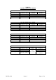
OPERATION
Having installed the transducers as instructed, they are ready for use. The transducer should not
be removed whilst the system is at pressure. Before applying power, check that the correct
polarity and excitation levels are being applied. See Table 1 for electrical connections.
CALIBRATION
Transducers are calibrated to the datum requested at time of order; this can be identified by the
sixth letter of the identification code as follows:-
A - Absolute datum
G - Gauge datum vented to atmosphere via the electrical connector or cable
LOAD CHARACTERISTICS (4-20mA Current Output)
The total resistive load in the loop (to include all the cable resistance) can be from 'zero to 50 x
(supply volts -7.5) ohms' e.g. with a 24V d.c. supply the permissible load is from zero up to 825
ohms.