
Safety Data Sheet
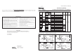

Dimensional Data (Cont.)
Type 5
.90”
(23 mm)
→
→
1.48”
(37.6 mm)
→
→
4.10”
(104 mm)
3.85”
(97.8 mm)
.85” Dia.
(21.6 mm)
↑
↓
.10”
(2.5 mm)
→
.33”
(8.4 mm)
→
→
→
Gasket, HNBR
(FDA Compliant)
Nut
5/8”-11
Note: Recommended hole size = 7/8” Dia. (Burr-Free)
1/32” to 5/32” tank wall
Type 10
All LS-7 Units: Install with float positioned as shown
for the required switch operation. Be sure that
markings on wrench flats are as follows: (1) Arrow
Vertical, (2) N.O. at top for N.O. operations, (3) N.C.
at top for N.C. operations
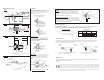
Type 7
Lead Wires
24” Extended 1/2” NPT
4-1/2”
5/8” (16 mm)
Wrench Flat
19/64”
(7.5 mm)
2-7/8”
(73 mm)
→
→
5/8”
1/2”
2-7/8”
4-1/4”
→
→
→
→
5/8”
Wrench Flat
1/2” NPT
Magnet
11/16”
Dia. Ref.
N.C. Actuation
Range
N.O.Actuation Range
Stainless Steel
Retaining Ring
#22 AWG Lead
Wires,Zip Cord
Style,24” - 27”
Extended
1.25”
Ref.
↓
↑
↓
↑
Units Shown Installed “Float Up”
for N.C. (Dry) Operation
N.C.
N.O.
Units Shown Installed “Float Down”
for N.O. (Dry) Operation
N.O.
N.C.
Types 3 and 4 Units
Assemble gasket (by user) on 5/8" - 11 threaded
mounting and install unit through
burr-free clear-
ance hole in tank side, from inside of tank. Lock in
place with HEX nut (supplied). Tighten to15 in./Ib.,
Max. Do not overtighten.
HEX
Locking Nut
Tank Side
Wrench
Flat
Gasket
(By User)
5/8” -
11 X 4/8” Thd.
Type 10 Units
Install unit in
burr-free 7/8" diameter hole in tank.
Gasket flange must rest firmly against tank wall. Turn
nut to compress seal. Tighten one-quarter turn past
hand-tight. Use wrench flat to hold housing, if
required.
Installation
Gasket
Flange
Tank Wall
(1/8” Nom.)
Switch
Housing
Nut
Washer
Compression Seal
in Sealed Position
Float
Assembly
LS-7 with Compression Seal (Type 10)
Type 12
Float Arc
Envelope
Sealing: When threading metal threads into a metal cou-
pling, pipe sealant or Teflon tape is recommended. Due to
potential compatibility problems, when sealing plastic
threaded units, a compatible pipe sealant such as No More
Leaks from Permatex is recommended.
Tightening (Plastic to Metal): When threading a plastic
level switch into a metal coupling, the installer should use a
suitable wrench and tighten the threads 1 to 1-1/2 additional
turns past hand-tight. Over-torquing of the threads will result
in damage to the plastic mounting plug.
Thread Treatment
Note:
.703” Dia. Thru Bore Required
Wrench
Flat
1/2”
NPT
5/8”
Max.
Tank Side
→
→
20
Pilot Duty
Volts
0-30
120
240
Amps AC
.4
.17
.080
Amps DC
.3
.13
.06
VA
Switch Ratings
- Maximum Resistive Load -
This product is suitable for Class I and Class II applications only, per the requirements of standard EN60730 and any additional
specific requirements for a particular application or medium being sensed. Class I compliance of metal bodied units requires
a ground connection between the metal body and the earthing system of the installation. Class I compliance of plastic bodied
units in contact with a conductive medium requires that the medium be effectively earthed so as to provide an earthed barrier
between the unit and accessible areas. For Class III compliance, a supply at safety extra-low voltage (SELV) must be provided.
Please consult the Factory for compliance information on specific part numbers.
Maintenance
Normally, no maintenance of any kind is required. When excessive contamination is present in the liquid, an
occasional wipe-down cleaning is all that
is needed.
Red
Red
N.O. or N.C. (Dry)
Typical Wiring Diagram
Electrical Connection
See Typical Wiring Diagram. Connect lead wires to load circuit, using approved method. Caution: See
“Specifications” (front page) and “Switch Ratings” (below) before connecting power.
Switch Operation
Depending on the mounting position, the float on these switches caneither rise or lower with the liquid level.
By rotating the switch 180°, the switch operation can be Normally Open or Normally Closed. Arrows on
exterior of mounting indicate N.O. when point up.
The switch is mounted so that the float lowers with the
liquid level. The switch is N.O.
Float Arc
Envelope
Normally
Open
Normally
Closed
The switch is mounted so that the float rises with the
liquid level. The switch is N.C.
Wrench
Flat