XT65/XT75 Siemens Cellular Engine Version: DocId: Supported Products: 00.130 XT65_XT75_HO_v00.
XT65/XT75 Hardware Interface Overview Document Name: XT65/XT75 Hardware Interface Overview Version: 00.130 Date: 2006-10-12 DocId: XT65_XT75_HO_v00.130 Status Confidential / Preliminary s Supported Products: XT65, XT75 General Notes Product is deemed accepted by Recipient and is provided without interface to Recipient´s products. The Product constitutes pre-release version and code and may be changed substantially before commercial release.
XT65/XT75 Hardware Interface Overview Contents s Contents 1 Introduction.............................................................................................................................................. 6 1.1 Related Documents......................................................................................................................... 6 1.2 Terms and Abbreviations ................................................................................................................ 7 1.
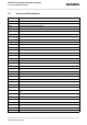
XT65/XT75 Hardware Interface Overview List of Tables s Tables Table 1: Table 2: Table 3: Table 4: Table 5: Table 6: Table 7: Table 8: Table 9: Table 10: Table 11: Table 12: Table 13: Table 14: Table 15: Table 16: Table 17: Table 18: Table 19: Table 20: Table 21: Table 22: Directives .................................................................................................................................... 10 Standards of North American type approval................................................
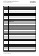
XT65/XT75 Hardware Interface Overview List of Figures s Figures Figure 1: Figure 2: Figure 3: Figure 4: Figure 5: Figure 6: Figure 7: Figure 8: Figure 9: Figure 10: Figure 11: Figure 12: Figure 13: Figure 14: Figure 15: Figure 16: GSM antenna connector placement ........................................................................................... 20 Figure 41: Restricted area around antenna pad ......................................................................... 21 GSM antenna pad placement ..
XT65/XT75 Hardware Interface Overview 1 Introduction 1 s Introduction This document applies to the following Siemens products: • • XT65 Module XT75 Module The document describes the hardware of the XT65 and XT75 modules, both designed to connect to a cellular device application and the air interface. It helps you quickly retrieve interface specifications, electrical and mechanical details and information on the requirements to be considered for integrating further components.
XT65/XT75 Hardware Interface Overview 1.2 Terms and Abbreviations 1.2 s Terms and Abbreviations Abbreviation Description ADC Analog-to-Digital Converter AGC Automatic Gain Control ANSI American National Standards Institute ARFCN Absolute Radio Frequency Channel Number ARP Antenna Reference Point ASC0 Asynchronous Controller.
XT65/XT75 Hardware Interface Overview 1.2 Terms and Abbreviations Abbreviation Description ESD Electrostatic Discharge ETS European Telecommunication Standard FCC Federal Communications Commission (U.S.
XT65/XT75 Hardware Interface Overview 1.
XT65/XT75 Hardware Interface Overview 1.3 Regulatory and Type Approval Information 1.3 s Regulatory and Type Approval Information 1.3.1 Directives and Standards XT65/XT75 is designed to comply with the directives and standards listed below. Please note that the product is still in a pre-release state and, therefore, type approval and testing procedures have not yet been completed.
XT65/XT75 Hardware Interface Overview 1.3 Regulatory and Type Approval Information s Table 3: Standards of European type approval GCF-CC V3.21.0 Global Certification Forum - Certification Criteria ETSI EN 301 489-1 V1.4.1 Candidate Harmonized European Standard (Telecommunications series) Electro Magnetic Compatibility and Radio spectrum Matters (ERM); Electro Magnetic Compatibility (EMC) standard for radio equipment and services; Part 1: Common Technical Requirements ETSI EN 301 489-7 V1.2.
XT65/XT75 Hardware Interface Overview 1.3 Regulatory and Type Approval Information 1.3.3 s SELV Requirements The power supply connected to the XT65/XT75 module shall be in compliance with the SELV requirements defined in EN 60950-1. See also Section 6.1 for further detail. 1.3.4 Safety Precautions The following safety precautions must be observed during all phases of the operation, usage, service or repair of any cellular terminal or mobile incorporating XT65/XT75.
XT65/XT75 Hardware Interface Overview 1.3 Regulatory and Type Approval Information s IMPORTANT! Cellular terminals or mobiles operate using radio signals and cellular networks. Because of this, connection cannot be guaranteed at all times under all conditions. Therefore, you should never rely solely upon any wireless device for essential communications, for example emergency calls.
XT65/XT75 Hardware Interface Overview 2 Product Concept 2 Product Concept 2.
XT65/XT75 Hardware Interface Overview 2.1 Key Features at a Glance Feature Implementation SMS Point-to-point MT and MO s Cell broadcast Text and PDU mode Storage: SIM card plus 25 SMS locations in mobile equipment Transmission of SMS alternatively over CSD or GPRS. Preferred mode can be user defined. Fax Group 3; Class 1 Audio Speech codecs: Half rate HR (ETS 06.20) Full rate FR (ETS 06.10) Enhanced full rate EFR (ETS 06.50/06.60/06.
XT65/XT75 Hardware Interface Overview 2.1 Key Features at a Glance s Feature Implementation SIM Application Toolkit SAT Release 99 TCP/IP stack Access by AT commands IP addresses IP version 4 Remote SIM Access XT65/XT75 supports Remote SIM Access. RSA enables XT65/XT75 to use a remote SIM card via its serial interface and an external application, in addition to the SIM card locally attached to the dedicated lines of the application interface.
XT65/XT75 Hardware Interface Overview 2.1 Key Features at a Glance Feature s Implementation Special features Charging Supports management of rechargeable Lithium Ion and Lithium Polymer batteries Real time clock Timer functions via AT commands GPIO 10 I/O pins of the application interface programmable as GPIO. Programming is done via AT commands. Alternatively, GPIO pin10 is configurable as pulse counter. Pulse counter Pulse counter for measuring pulse rates from 0 to 1000 pulses per second.
XT65/XT75 Hardware Interface Overview 3 Application Interface 3 s Application Interface XT65/XT75 is equipped with an 80-pin board-to-board connector that connects to the external application and incorporates several sub-interfaces: power supply, charger interface, SIM interface, serial interface ASC0, serial interface USB, serial interface I²C/SPI, two analog audio interfaces, digital audio interface (DAI), 10 lines GPIO interface, as well as status and control lines: IGT, EMERG_RST, PWR_IND, SYNC (for
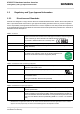
XT65/XT75 Hardware Interface Overview 3.1 Operating Modes 3.1 s Operating Modes The table below briefly summarizes the various operating modes available for the module. Table 5: Overview of operating modes Normal operation GSM / GPRS SLEEP Various power save modes set with AT+CFUN command. Software is active to minimum extent. If the module was registered to the GSM network in IDLE mode, it is registered and paging with the BTS in SLEEP mode, too.
s XT65/XT75 Hardware Interface Overview 4 GSM Antenna Interface 4 GSM Antenna Interface The GSM interface has an impedance of 50Ω. XT65/XT75 is capable of sustaining a total mismatch at the antenna connector without any damage, even when transmitting at maximum RF power. DC electric strength is given (see Table 11). The external antenna must be matched properly to achieve best performance regarding radiated power, DCpower consumption, modulation accuracy and harmonic suppression.
s XT65/XT75 Hardware Interface Overview 4.2 Antenna Pad Antenna connected to Hirose connector: Antenna or Measurement Equipment Module PAD Antenna connected to pad: U.FL PAD U.FL 50Ohm 50Ohm 50Ohm Module Z Antenna Z 50Ohm Figure 40: Never use antenna connector and antenna pad at the same time 4.2 Antenna Pad The antenna can be soldered to the pad, or attached via contact springs.
XT65/XT75 Hardware Interface Overview 4.2 Antenna Pad s Also, consider that according to the GSM recommendations TS 45.005 and TS 51.010-01 a 50Ω connector is mandatory for type approval measurements. This requires GSM devices with an integral antenna to be temporarily equipped with a suitable connector or a low loss RF cable with adapter.
s XT65/XT75 Hardware Interface Overview 4.3 Antenna Connector 4.3 Antenna Connector For GSM and GPS, XT65/XT75 uses an ultra-miniature SMT antenna connector supplied from Hirose Ltd. The product name is: • U.FL-R-SMT The position of the antenna connector on the XT65/XT75 board can be seen in Section 4.1. Figure 4: Mechanical dimensions of U.FL-R-SMT connector Table 7: Product specifications of U.
s XT65/XT75 Hardware Interface Overview 4.3 Antenna Connector Table 7: Product specifications of U.FL-R-SMT connector Item Specification Conditions Temperature cycle No damage, cracks and looseness of parts. Contact resistance: Center 25mΩ Outside 15mΩ Temperature: +40°C → 5 to 35°C → +90°C → 5 to 35°C Time: 30min → within 5min → 30min within 5min Salt spray test No excessive corrosion 48 hours continuous exposure to 5% salt water Table 8: Material and finish of U.
XT65/XT75 Hardware Interface Overview 4.3 Antenna Connector s In addition to the connectors illustrated above, the U.FL-LP-(V)-040(01) version is offered as an extremely space saving solution. This plug is intended for use with extra fine cable (up to ; 0.81mm) and minimizes the mating height to 2mm. See Figure 46 which shows the Hirose datasheet. Figure 7: Specifications of U.FL-LP-(V)-040(01) plug XT65_XT75_HO_v00.
s XT65/XT75 Hardware Interface Overview 4.3 Antenna Connector Table 9: Ordering information for Hirose U.FL Series Item Part number HRS number Connector on XT65/XT75 U.FL-R-SMT CL331-0471-0-10 Right-angle plug shell for ; 0.81mm cable U.FL-LP-040 CL331-0451-2 Right-angle plug for ; 0.81mm cable U.FL-LP(V)-040 (01) CL331-053-8-01 Right-angle plug for ; 1.13mm cable U.FL-LP-068 CL331-0452-5 Right-angle plug for ; 1.32mm cable U.FL-LP-066 CL331-0452-5 Extraction jig E.
XT65/XT75 Hardware Interface Overview 5 GPS Antenna Interface 5 s GPS Antenna Interface In order to receive satellite signals an additional GPS antenna must be connected to the GPS part of the XT65/ XT75 module. 5.1 Antenna Installation To suit the physical design of individual applications XT65/XT75 offers two alternative approaches to connecting the antenna: • Recommended approach: U.FL-R-SMT antenna connector from Hirose assembled on the component side of the PCB.
s XT65/XT75 Hardware Interface Overview 5.2 GPS Antenna 5.2 GPS Antenna It is possible to connect active or passive GPS antennas. In either case they must have 50 Ohm impedance. The application should be designed in a way to achieve a minimum of 6dB decoupling between the GSM/DCS/PCS antenna path and the GPS antenna path. Please note that the GPS antenna must be isolated for ESD protection (to withstand a voltage resistance up to 8kV air discharge).
s XT65/XT75 Hardware Interface Overview 6 Electrical, Reliability and Radio Characteristics 6 Electrical, Reliability and Radio Characteristics 6.1 Absolute Maximum Ratings The absolute maximum ratings stated in Table 11 are stress ratings under any conditions. Stresses beyond any of these limits will cause permanent damage to XT65/XT75. The power supply connected to the XT65/XT75 module shall be compliant with the SELV requirements defined in EN60950.
s XT65/XT75 Hardware Interface Overview 6.2 Operating Temperatures 6.2 Operating Temperatures Table 12: Board temperature Parameter Min Typ Max Unit Temperature measured on XT65/XT75 board -30 --- >+80 °C Temperature measured at battery NTC -20 --- +60 Automatic shutdown1 1. Due to temperature measurement uncertainty, a tolerance on the stated shutdown thresholds may occur.
s XT65/XT75 Hardware Interface Overview 6.3 Storage Conditions 6.3 Storage Conditions The conditions stated below are only valid for modules in their original packed state in weather protected, nontemperature-controlled storage locations. Normal storage time under these conditions is 12 months maximum. Table 15: Storage conditions Type Condition Unit Reference Air temperature: Low -40 °C ETS 300 019-2-1: T1.2, IEC 68-2-1 Ab High +85 Humidity relative: Low Air pressure: ETS 300 019-2-1: T1.
s XT65/XT75 Hardware Interface Overview 6.4 Reliability Characteristics 6.4 Reliability Characteristics The test conditions stated below are an extract of the complete test specifications. Table 16: Summary of reliability test conditions Type of test Conditions Standard Vibration Frequency range: 10-20Hz; acceleration: 3.
s XT65/XT75 Hardware Interface Overview 6.5 Pin Assignment and Signal Description 6.5 Pin Assignment and Signal Description The Molex board-to-board connector on XT65/XT75 is an 80-pin double-row receptacle. The position of the board-to-board connector can be seen in Figure 11 that shows the top view of XT65/XT75.
s XT65/XT75 Hardware Interface Overview 6.5 Pin Assignment and Signal Description Please note that the reference voltages listed in Table 17 are the values measured directly on the XT65/XT75 module. They do not apply to the accessories connected. Table 17: Signal description Function Signal name IO Signal form and level Comment Power supply BATT+ I VI = 3.3V to 4.5V Five pins of BATT+ and GND must be connected in parallel for supply purposes because higher peak currents may occur. VItyp = 3.
s XT65/XT75 Hardware Interface Overview 6.5 Pin Assignment and Signal Description Table 17: Signal description Function Signal name IO Signal form and level Comment Power indicator PWR_IND O VIHmax = 10V PWR_IND (Power Indicator) notifies the module’s on/off state. VOLmax = 0.4V at Imax = 2mA PWR_IND is an open collector that needs to be connected to an external pull-up resistor. Low state of the open collector indicates that the module is on.
s XT65/XT75 Hardware Interface Overview 6.5 Pin Assignment and Signal Description Table 17: Signal description Function Signal name IO Signal form and level Comment Synchronization SYNC O VOLmax = 0.3V at I = 0.1mA There are two alternative options for using the SYNC pin: VOHmin = 2.3V at I = -0.1mA VOHmax = 3.05V n Tx = n x 577µs impulse each 4.616ms, with 180µs forward time. a) Indicating increased current consumption during uplink transmission burst.
s XT65/XT75 Hardware Interface Overview 6.5 Pin Assignment and Signal Description Table 17: Signal description Function Signal name IO Signal form and level Comment SIM interface specified for use with 3V SIM card CCIN I RI ≈ 100kΩ VILmax = 0.6V at I = -25µA VIHmin = 2.1V at I = -10µA VOmax = 3.05V CCIN = Low, SIM card holder closed CCRST O RO ≈ 47Ω VOLmax = 0.25V at I = +1mA VOHmin = 2.5V at I = -0.5mA VOHmax = 2.95V CCIO I/O RI ≈ 4.7kΩ VILmax = 0.75V VILmin = -0.3V VIHmin = 2.
s XT65/XT75 Hardware Interface Overview 6.5 Pin Assignment and Signal Description Table 17: Signal description Function Signal name IO Signal form and level Comment SIM interface specified for use with 1.8V SIM card CCIN I RI ≈ 100kΩ VILmax = 0.6V at I = -25µA VIHmin = 2.1V at I = -10µA VOmax = 3.05V CCIN = Low, SIM card holder closed CCRST O RO ≈ 47Ω VOLmax = 0.25V at I = +1mA VOHmin = 1.45V at I = -0.5mA VOHmax = 1.90V CCIO I/O RI ≈ 4.7kΩ VILmax = 0.45V VIHmin = 1.
s XT65/XT75 Hardware Interface Overview 6.5 Pin Assignment and Signal Description Table 17: Signal description Function Signal name IO Signal form and level Comment SPI SPIDI I Serial Peripheral Interface I2CDAT_SPIDO O VOLmax = 0.2V at I = 2mA VOHmin = 2.55V at I = -0.5mA VOHmax = 3.05V If the Serial Peripheral Interface is active the I2C interface is not available. SPICS O VILmax = 0.8V VIHmin = 2.15V, VIHmax = VEXTmin + 0.3V = 3.05V USB VUSB_IN I VINmin = 4.0V VINmax = 5.
s XT65/XT75 Hardware Interface Overview 6.5 Pin Assignment and Signal Description Table 17: Signal description Function Signal name Analog ADC1_IN Digital Converter ADC2_IN IO Signal form and level Comment I Input voltage: VImin = 0V, VImax = 2.4V Inputs used for measuring external voltages. In the range of 0mV to 2400mV.
s XT65/XT75 Hardware Interface Overview 6.5 Pin Assignment and Signal Description Table 17: Signal description Function Signal name IO Signal form and level Comment Analog Audio interface VMIC O VOmin = 2.4V VOtyp = 2.5V VOmax = 2.6V Imax = 2mA Microphone supply for customer feeding circuits EPP2 O EPN2 O 3.0Vpp differential typical @ 0dBm0 The audio output can directly operate a 32-Ohm-loudspeaker. 4.2Vpp differential maximal @ If unused keep pins open. 3.
XT65/XT75 Hardware Interface Overview 6.5 Pin Assignment and Signal Description 1. s Restrictions during SLEEP mode: During SLEEP Mode the ADC is shut down temporarily (per default). Please make sure that during SLEEP Mode shutdown the ADCx_IN input voltage does not exceed ±0.3V. The input current (reverse feeding) may reach 3mA! If SLEEP Mode is activated there are three protection possibilities: - Use an RC combination for current limitation.
s XT65/XT75 Hardware Interface Overview 6.6 Power Supply Ratings 6.6 Power Supply Ratings Table 18: Power supply ratings Parameter Description Conditions Min Typ Max Unit BATT+ Supply voltage Directly measured at reference point TP 3.3 BATT+ and TP GND. 3.8 4.5 V 400 mV @ f<200kHz 50 mV @ f>200kHz 2 mV Voltage must stay within the min/max values, including voltage drop, ripple, spikes.
XT65/XT75 Hardware Interface Overview 7 Mechanics 7 Mechanics 7.1 Mechanical Dimensions of XT65/XT75 s Figure 11 shows the top view of XT65/XT75 and provides an overview of the board's mechanical dimensions. For further details see Figure 12. Length: 55.00mm Width: 33.90mm Height: 3.15mm Pin1 Pin80 Figure 11: XT65/XT75– top view XT65_XT75_HO_v00.
s XT65/XT75 Hardware Interface Overview 7.1 Mechanical Dimensions of XT65/XT75 Figure 12: Dimensions of XT65/XT75 (all dimensions in mm) XT65_XT75_HO_v00.
XT65/XT75 Hardware Interface Overview 7.2 Mounting XT65/XT75 to the Application Platform 7.2 s Mounting XT65/XT75 to the Application Platform There are many ways to properly install XT65/XT75 in the host device. An efficient approach is to mount the XT65/XT75 PCB to a frame, plate, rack or chassis. Fasteners can be M2 screws plus suitable washers, circuit board spacers, or customized screws, clamps, or brackets. In addition, the board-to-board connection can also be utilized to achieve better support.
XT65/XT75 Hardware Interface Overview 7.3 Board-to-Board Application Connector 7.3 s Board-to-Board Application Connector This section provides the specifications of the 80-pin board-to-board connector used to connect XT65/XT75 to the external application. Connector mounted on the XT65/XT75 module: Type: 52991-0808 SlimStack Receptacle 80 pins, 0.50mm pitch, for stacking heights from 3.0 to 4.0mm, see Figure 14 for details. Supplier: Molex, http//www.molex.
XT65/XT75 Hardware Interface Overview 7.3 Board-to-Board Application Connector s Mating connector types for the customer's application offered by Molex: Figure 13: Mating board-to-board connector 53748-0808 on application • • 53748-0808 SlimStack Plug, 3mm stacking height, see Figure 15 for details. 53916-0808 SlimStack Plug, 4mm stacking height XT65_XT75_HO_v00.
XT65/XT75 Hardware Interface Overview 7.3 Board-to-Board Application Connector s Figure 14: Molex board-to-board connector 52991-0808 on XT65/XT75 XT65_XT75_HO_v00.
XT65/XT75 Hardware Interface Overview 7.3 Board-to-Board Application Connector s Figure 15: Mating board-to-board connector 53748-0808 on application XT65_XT75_HO_v00.
s XT65/XT75 Hardware Interface Overview 8 Reference Approval 8 Reference Approval 8.1 Reference Equipment for Type Approval The Siemens reference setup submitted to type approve XT65/XT75 consists of the following components: • • • • • • • Siemens XT65/XT75 cellular engine Development Support Box DSB75 SIM card reader integrated on DSB75 U.FL-R-SMT antenna connector and U.FL-LP antenna cable Handset type Votronic HH-SI-30.3/V1.
XT65/XT75 Hardware Interface Overview 8.2 Compliance with FCC Rules and Regulations 8.2 s Compliance with FCC Rules and Regulations The Equipment Authorization Certification for the Siemens reference application described in Section 8.
XT65/XT75 Hardware Interface Overview 9 Appendix 9 Appendix 9.
XT65/XT75 Hardware Interface Overview 9.1 List of Parts and Accessories s Table 21: Molex sales contacts (subject to change) Molex Molex Deutschland GmbH American Headquarters For further information please click: Felix-Wankel-Str. 11 4078 Heilbronn-Biberach Germany Lisle, Illinois 60532 U.S.A. http://www.molex.com Phone: +49-7066-9555 0 Fax: +49-7066-9555 29 Email: mxgermany@molex.com Molex China Distributors Beijing, Room 1319, Tower B, COFCO Plaza No.
XT65/XT75 Hardware Interface Overview 9.2 Fasteners and Fixings for Electronic Equipment 9.2 s Fasteners and Fixings for Electronic Equipment This section provides a list of suppliers and manufacturers offering fasteners and fixings for electronic equipment and PCB mounting. The content of this section is designed to offer basic guidance to various mounting solutions with no warranty on the accuracy and sufficiency of the information supplied.
XT65/XT75 Hardware Interface Overview 9.2 Fasteners and Fixings for Electronic Equipment Article number: 07.51.403 s Insulating Spacer for M2 Self-gripping1 Length 3.0mm Material Polyamide 6.6 Surface Black Internal diameter 2.2mm External diameter 4.0mm Flammability rating UL94-HB 1. 2 spacers are delivered with DSB75 Support Board Article number: 05.11.209 Threaded Stud M2.5 - M2 Type E / External thread at both ends Length 3.
XT65/XT75 Hardware Interface Overview 9.2 Fasteners and Fixings for Electronic Equipment Article number: 01.14.131 s Screw M21 DIN 84 - ISO 1207 Length 8.0mm Material Steel 4.8 Surface Zinced A2K Thread M2 Head diameter D = 3.8mm Head height 1.30mm Type Slotted cheese head screw 1. 2 screws are delivered with DSB75 Support Board Article number: 01.14.141 Screw M2 DIN 84 - ISO 1207 Length 10.0mm Material Steel 4.8 Surface Zinced A2K Thread M2 Head diameter D = 3.
XT65/XT75 Hardware Interface Overview 9.2 Fasteners and Fixings for Electronic Equipment Article number: 02.10.011 s Hexagon Nut1 DIN 934 - ISO 4032 Material Steel 4.8 Surface Zinced A2K Thread M2 Wrench size / ; 4 Thickness / L 1.6mm Type Nut DIN/UNC, DIN934 1. 2 nuts are delivered with DSB75 Support Board XT65_XT75_HO_v00.