PHS8-P Version: DocId: 01.000 PHS8-P_HIO_v01.
PHS8-P Hardware Interface Overview 2 Document Name: PHS8-P Hardware Interface Overview Version: 01.000 Date: 2011-11-10 DocId: PHS8-P_HIO_v01.000 Status Confidential / Released GENERAL NOTE THE USE OF THE PRODUCT INCLUDING THE SOFTWARE AND DOCUMENTATION (THE "PRODUCT") IS SUBJECT TO THE RELEASE NOTE PROVIDED TOGETHER WITH PRODUCT. IN ANY EVENT THE PROVISIONS OF THE RELEASE NOTE SHALL PREVAIL. THIS DOCUMENT CONTAINS INFORMATION ON CINTERION PRODUCTS.
PHS8-P Hardware Interface Overview Contents 41 Contents 1 Introduction ................................................................................................................. 6 1.1 Related Documents ........................................................................................... 6 1.2 Terms and Abbreviations ................................................................................... 6 1.3 Regulatory and Type Approval Information .............................................
PHS8-P Hardware Interface Overview Tables 41 Tables Table 1: Table 2: Table 3: Table 4: Table 5: Table 6: Table 7: Table 8: Table 9: Table 10: Table 11: Table 12: Table 13: Directives ....................................................................................................... Standards of North American type approval .................................................. Standards of European type approval............................................................ Requirements of quality ......
PHS8-P Hardware Interface Overview Figures 41 Figures Figure 1: Figure 2: Figure 3: Figure 4: Figure 5: Figure 6: Figure 7: Figure 8: Figure 9: Figure 10: Figure 11: PHS8-P system overview............................................................................... Decoupling capacitor(s) for BATT+................................................................ USB circuit ..................................................................................................... Serial interface ASC0......
PHS8-P Hardware Interface Overview 1 Introduction 15 1 Introduction The document1 describes the hardware of the PHS8-P module, designed to connect to a cellular device application and the air interface. It helps you quickly retrieve interface specifications, electrical and mechanical details and information on the requirements to be considered for integrating further components. 1.
PHS8-P Hardware Interface Overview 1.
PHS8-P Hardware Interface Overview 1.2 Terms and Abbreviations 15 Abbreviation Description NMEA National Marine Electronics Association NTC Negative Temperature Coefficient PBCCH Packet Switched Broadcast Control Channel PCB Printed Circuit Board PCL Power Control Level PCM Pulse Code Modulation PCS Personal Communication System, also referred to as GSM 1900 PD Pull Down resistor (appr.
PHS8-P Hardware Interface Overview 1.2 Terms and Abbreviations 15 Abbreviation Description UL Upload UMTS Universal Mobile Telecommunications System URC Unsolicited Result Code USB Universal Serial Bus UICC USIM Integrated Circuit Card USIM UMTS Subscriber Identification Module WCDMA Wideband Code Division Multiple Access PHS8-P_HIO_v01.
PHS8-P Hardware Interface Overview 1.3 Regulatory and Type Approval Information 15 1.3 Regulatory and Type Approval Information 1.3.1 Directives and Standards PHS8-P has been designed to comply with the directives and standards listed below.
PHS8-P Hardware Interface Overview 1.3 Regulatory and Type Approval Information 15 Table 3: Standards of European type approval ETSI EN 301 489-03 V1.4.1 Electromagnetic Compatibility and Radio spectrum Matters (ERM); Electromagnetic Compatibility (EMC) standard for radio equipment and services; Part 3: Specific conditions for Short-Range Devices (SRD) operating on frequencies between 9 kHz and 40 GHz ETSI EN 301 489-07 V1.3.
PHS8-P Hardware Interface Overview 1.3 Regulatory and Type Approval Information 15 Table 6: Toxic or hazardous substances or elements with defined concentration limits PHS8-P_HIO_v01.
PHS8-P Hardware Interface Overview 1.3 Regulatory and Type Approval Information 15 1.3.2 SAR requirements specific to portable mobiles Mobile phones, PDAs or other portable transmitters and receivers incorporating a GSM module must be in accordance with the guidelines for human exposure to radio frequency energy. This requires the Specific Absorption Rate (SAR) of portable PHS8-P based applications to be evaluated and approved for compliance with national and/or international regulations.
PHS8-P Hardware Interface Overview 1.3 Regulatory and Type Approval Information 15 1.3.3 SELV Requirements The power supply connected to the PHS8-P module shall be in compliance with the SELV requirements defined in EN 60950-1. 1.3.4 Safety Precautions The following safety precautions must be observed during all phases of the operation, usage, service or repair of any cellular terminal or mobile incorporating PHS8-P.
PHS8-P Hardware Interface Overview 1.3 Regulatory and Type Approval Information 15 IMPORTANT! Cellular terminals or mobiles operate using radio signals and cellular networks. Because of this, connection cannot be guaranteed at all times under all conditions. Therefore, you should never rely solely upon any wireless device for essential communications, for example emergency calls.
PHS8-P Hardware Interface Overview 2 Product Concept 19 2 Product Concept 2.
PHS8-P Hardware Interface Overview 2.
PHS8-P Hardware Interface Overview 2.1 Key Features at a Glance 19 Feature Implementation Interfaces Module interface Surface mount device with solderable connection pads (SMT application interface). Land grid array (LGA) technology ensures high solder joint reliability and provides the possibility to use an optional module mounting socket. For more information on how to integrate SMT modules see also [11].
PHS8-P Hardware Interface Overview 2.2 PHS8-P System Overview 19 2.
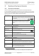
PHS8-P Hardware Interface Overview 3 Application Interface 29 3 Application Interface PHS8-P is equipped with an SMT application interface that connects to the external application. The host interface incorporates several sub-interfaces described in the following sections: • • • • • • • Operating modes - see Section 3.1 Power supply - see Section 3.2 Serial interface USB - see Section 3.3 Serial interface ASC0 - Section 3.4 UICC/SIM/USIM interface - see Section 3.
PHS8-P Hardware Interface Overview 3.1 Operating Modes 29 3.1 Operating Modes The table below briefly summarizes the various operating modes referred to in the following chapters. Table 7: Overview of operating modes Mode Function Normal GSM / operation GPRS / UMTS / HSPA SLEEP Power saving set automatically when no call is in progress and the USB connection is suspended by host or not present and no active communication via ASC0.
PHS8-P Hardware Interface Overview 3.2 Power Supply 29 3.2 Power Supply PHS8-P needs to be connected to a power supply at the SMT application interface - 6 lines each BATT+ and GND. There are three separate voltage domains for BATT+: • BATT+_WCDMA with 2 lines for the WCDMA power amplifier supply • BATT+_GSM with 2 lines for the GSM power amplifier supply • BATT+ with 2 lines for the general power management.
PHS8-P Hardware Interface Overview 3.3 USB Interface 29 3.3 USB Interface PHS8-P supports a USB 2.0 High Speed (480Mbit/s) device interface that is Full Speed (12Mbit/s) compliant. The USB interface is primarily intended for use as command and data interface and for downloading firmware. The USB host is responsible for supplying the VUSB_IN line. This line is for voltage detection only. The USB part (driver and transceiver) is supplied by means of BATT+.
PHS8-P Hardware Interface Overview 3.4 Serial Interface ASC0 29 3.4 Serial Interface ASC0 PHS8-P offers an 8-wire unbalanced, asynchronous modem interface ASC0 conforming to ITU-T V.24 protocol DCE signalling. The electrical characteristics do not comply with ITU-T V.28. The significant levels are 0V (for low data bit or active state) and 1.8V (for high data bit or inactive state). PHS8-P is designed for use as a DCE.
PHS8-P Hardware Interface Overview 3.4 Serial Interface ASC0 29 Table 8: DCE-DTE wiring of ASC0 V.24 circuit DCE DTE Line function Signal direction Line function Signal direction 103 TXD0 Input TXD Output 104 RXD0 Output RXD Input 105 RTS0 Input RTS Output 106 CTS0 Output CTS Input 108/2 DTR0 Input DTR Output 107 DSR0 Output DSR Input 109 DCD0 Output DCD Input 125 RING0 Output RING Input PHS8-P_HIO_v01.
PHS8-P Hardware Interface Overview 3.5 UICC/SIM/USIM Interface 29 3.5 UICC/SIM/USIM Interface PHS8-P has an integrated UICC/SIM/USIM interface compatible with the 3GPP 31.102 and ETSI 102 221. This is wired to the host interface in order to be connected to an external SIM card holder. Five pads on the SMT application interface are reserved for the SIM interface. The UICC/SIM/USIM interface supports 3V and 1.8V SIM cards.
PHS8-P Hardware Interface Overview 3.5 UICC/SIM/USIM Interface 29 open: Card removed closed: Card inserted Module SMT application interface CCIN CCRST 1n CCCLK SIM / UICC GND CCIO CCVCC 220n Figure 5: UICC/SIM/USIM interface The total cable length between the SMT application interface pads on PHS8-P and the pads of the external SIM card holder must not exceed 100mm in order to meet the specifications of 3GPP TS 51.010-1 and to satisfy the requirements of EMC compliance.
PHS8-P Hardware Interface Overview 3.6 Analog Audio Interface 29 3.6 Analog Audio Interface PHS8-P has an analog audio interface with a balanced analog microphone input and a balanced analog earpiece output. A supply voltage and an analog ground connection are provided at dedicated lines. PHS8-P offers eight audio modes which can be selected with the AT^SNFS command. The electrical characteristics of the voiceband part vary with the audio mode.
PHS8-P Hardware Interface Overview 4 GPS Receiver 29 4 GPS Receiver PHS8-P integrates a GPS receiver that offers the full performance of GPS technology. The GPS receiver is able to continuously track all satellites in view, thus providing accurate satellite position data. The integrated GPS receiver supports the NMEA protocol via USB or ASC0 interface. NMEA is a combined electrical and data specification for communication between various (marine) electronic devices including GPS receivers.
PHS8-P Hardware Interface Overview 5 Antenna Interfaces 33 5 Antenna Interfaces 5.1 GSM/UMTS Antenna Interface The PHS8-P GSM/UMTS antenna interface comprises a main GSM/UMTS antenna as well as an optional UMTS Rx diversity antenna to improve signal reliability and quality1. The interface has an impedance of 50Ω. PHS8-P is capable of sustaining a total mismatch at the antenna interface without any damage, even when transmitting at maximum RF power.
PHS8-P Hardware Interface Overview 5.1 GSM/UMTS Antenna Interface 33 5.1.1 Antenna Installation The antenna is connected by soldering the antenna pads and their neighboring ground pads directly to the application’s PCB. The distance between the antenna pads and their neighboring GND pads has been optimized for best possible impedance. To prevent mismatch, special attention should be paid to these pads on the application’ PCB.
PHS8-P Hardware Interface Overview 5.2 GPS Antenna Interface 33 5.2 GPS Antenna Interface In addition to the RF antenna interface PHS8-P also has a GPS antenna interface. The GPS antenna installation and connector are the same as for the RF antenna interface (see Section 5.1.1). It is possible to connect active or passive GPS antennas. In either case they must have 50 Ohm impedance. The simultaneous operation of GSM and GPS has been implemented.
PHS8-P Hardware Interface Overview 5.2 GPS Antenna Interface 33 Figure 7 shows sample circuits realizing ESD protection for a passive GPS antenna. Module SMT interface VGPS 47pF Not used ANT_GPS_DC (Optional) 0R ESD protection Passive GPS antenna 10nH ANT_GPS 2p2 Figure 7: ESD protection for passive GPS antenna PHS8-P_HIO_v01.
PHS8-P Hardware Interface Overview 6 Mechanics 35 6 Mechanics 6.1 Mechanical Dimensions of PHS8-P Figure 8 shows the top view of PHS8-P and provides an overview of the board's mechanical dimensions. For further details see Figure 9. Length: 33mm Width: 29mm Height: 2mm Top view Bottom view Figure 8: PHS8-P – top view PHS8-P_HIO_v01.
PHS8-P Hardware Interface Overview 6.1 Mechanical Dimensions of PHS8-P 35 Position marker Internal use; Not to be soldered Figure 9: Dimensions of PHS8-P (all dimensions in mm) PHS8-P_HIO_v01.
PHS8-P Hardware Interface Overview 7 Sample Application 37 7 Sample Application Figure 10 shows a typical example of how to integrate an PHS8-P module with an application. The audio interface demonstrates the balanced connection of microphone and earpiece. This solution is particularly well suited for internal transducers. The PWR_IND line is an open collector that needs an external pull-up resistor which connects to the voltage supply VCC µC of the microcontroller.
PHS8-P Hardware Interface Overview 7 Sample Application 37 PHS8 Sample Application Current limiter <60mA ANT_GSM VGPS ANT_DRX ANT_GPS BC847 47k 47k 2 EMERG_RST BC847 2 2 VCC µC 100k PWR_IND VDD (1.8V) 100µF ...220µF ultra low ESR VEXT (1.8V) 1µF VCC µC VCCA 8 OE VCCB 1µF 8 Level Controller 2 CCIN CCVCC CCRST EPP CCCLK AGND 220nF 1nF Figure 10: PHS8-P sample application PHS8-P_HIO_v01.
PHS8-P Hardware Interface Overview 8 Reference Approval 39 8 Reference Approval 8.1 Reference Equipment for Type Approval The Cinterion Wireless Modules reference setup submitted to type approve PHS8-P is shown in the following figure1. The module (i.e., the evaluation module) is connected to the DSB75 via a special adapter and either mounted directly onto the adapter or connected using a flex cable: A udio test equipm ent V otronic handset an alo ga ud io D etail: If u sin g Hirose U .
PHS8-P Hardware Interface Overview 8.2 Compliance with FCC and IC Rules and Regulations 39 8.2 Compliance with FCC and IC Rules and Regulations The Equipment Authorization Certification for the Cinterion Wireless Modules reference application described in Section 8.
PHS8-P Hardware Interface Overview 9 Appendix 41 9 Appendix 9.
PHS8-P Hardware Interface Overview 9.1 List of Parts and Accessories 41 Table 12: Molex sales contacts (subject to change) Molex For further information please click: http://www.molex.com Molex Deutschland GmbH Otto-Hahn-Str. 1b 69190 Walldorf Germany Phone: +49-6227-3091-0 Fax: +49-6227-3091-8100 Email: mxgermany@molex.com American Headquarters Lisle, Illinois 60532 U.S.A. Phone: +1-800-78MOLEX Fax: +1-630-969-1352 Molex China Distributors Beijing, Room 1311, Tower B, COFCO Plaza No.