
User's Manual


Table Of Contents
PH8/PH8-P Hardware Interface Overview
5 Antenna Interfaces
34
PH8_PH8-P_HD_v02.000 Page 29 of 46 2011-10-21
Confidential / Released
5 Antenna Interfaces
5.1 GSM/UMTS Antenna Interface
The PH8/PH8-P GSM/UMTS antenna interface comprises a main GSM/UMTS antenna as well
as an optional UMTS Rx diversity antenna to improve signal reliability and quality
1
. The inter-
face has an impedance of 50Ω. PH8/PH8-P is capable of sustaining a total mismatch at the
antenna interface without any damage, even when transmitting at maximum RF power.
The external antenna must be matched properly to achieve best performance regarding radi-
ated power, DC-power consumption, modulation accuracy and harmonic suppression. Match-
ing networks are not included on the PH8/PH8-P PCB and should be placed in the host
application, if the antenna does not have an impendance of 50Ω.
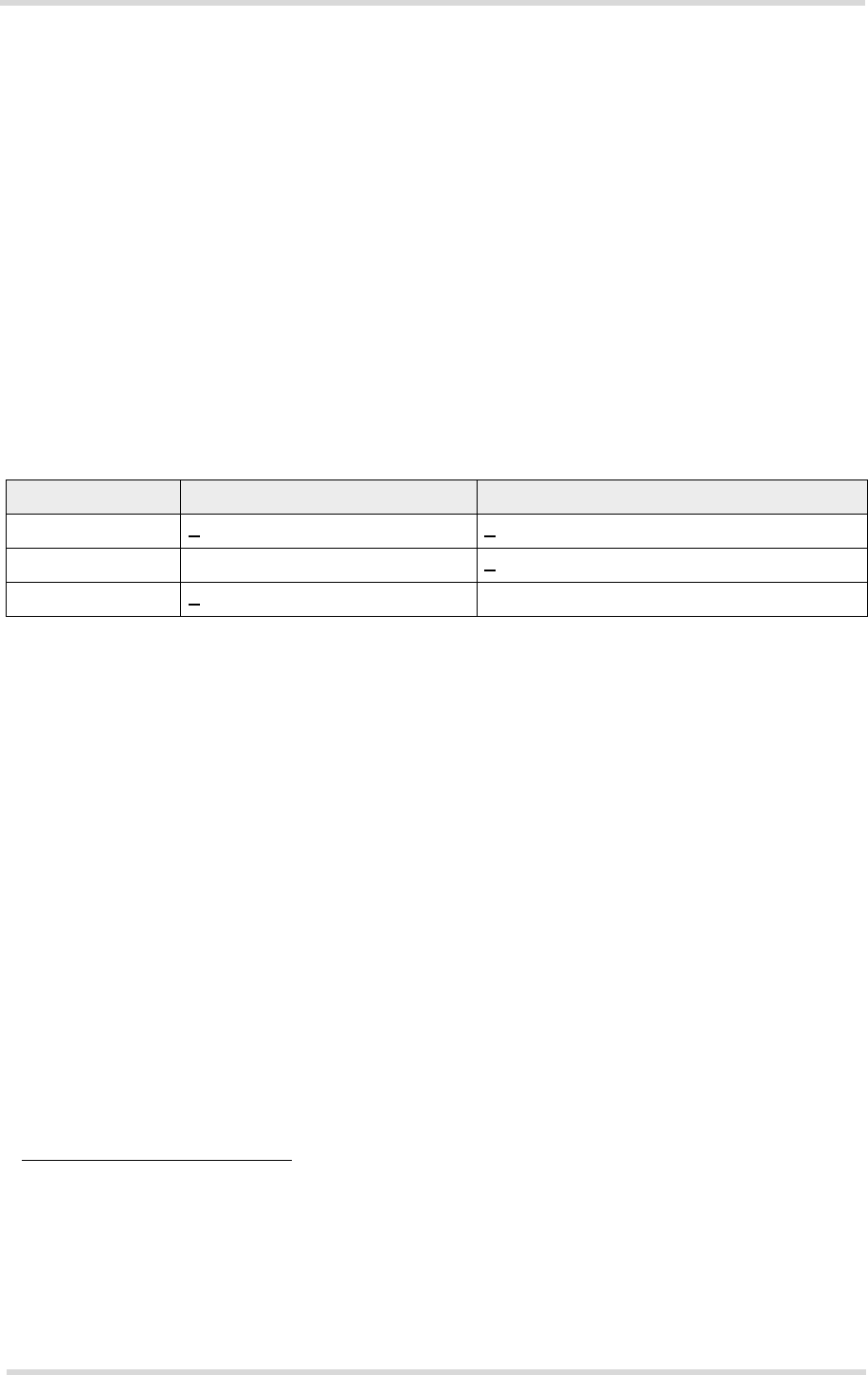
Regarding the return loss PH8/PH8-P provides the following values in the active band:
The connection of the antenna or other equipment must be decoupled from DC voltage. This
is necessary because the antenna connector is DC coupled to ground via an inductor for ESD
protection.
5.1.1 Antenna Installation
The U.FL antenna connector from Hirose/Molex of the main GSM/UMTS antenna has been
chosen as antenna reference point (ARP) for the Cinterion Wireless Modules reference equip-
ment submitted to type approve PH8/PH8-P. See Section 5.1.2 for details. All RF data specified
throughout this manual is related to the ARP. The positions of the module’s antenna connectors
can be seen in Figure 9.
1.
By delivery default the optional UMTS Rx diversity antenna is configured as available for the module. To
avoid negative side effects and performance degradation it is recommended to disable the diversity an-
tenna path if
- the host application does not support a diversity antenna
- the host application includes a diversity antenna - but a 3G network simulator is used for development
and performance tests.
Please refer to [1] for details on how to configure antenna settings.
Table 10: Return loss in the active band
State of module Return loss of module Recommended return loss of application
Receive >
8dB > 12dB
Transmit not applicable >
12dB
Idle <
5dB not applicable