Cinterion® PDS5-E/PDS5-US Hardware Interface Overview Version: DocId: 02.800 PDS5_HIO_v02.800 M2M.GEMALTO.
Cinterion® PDS5-E/PDS5-US Hardware Interface Overview Page 2 of 37 2 Document Name: Cinterion® PDS5-E/PDS5-US Hardware Interface Overview Version: 02.800 Date: 2014-10-24 DocId: PDS5_HIO_v02.800 Status Confidential / Preliminary GENERAL NOTE THE USE OF THE PRODUCT INCLUDING THE SOFTWARE AND DOCUMENTATION (THE "PRODUCT") IS SUBJECT TO THE RELEASE NOTE PROVIDED TOGETHER WITH PRODUCT. IN ANY EVENT THE PROVISIONS OF THE RELEASE NOTE SHALL PREVAIL.
Cinterion® PDS5-E/PDS5-US Hardware Interface Overview Page 3 of 37 Trademark Notice Gemalto, the Gemalto logo, are trademarks and service marks of Gemalto and are registered in certain countries. Microsoft and Windows are either registered trademarks or trademarks of Microsoft Corporation in the United States and/or other countries. All other registered trademarks or trademarks mentioned in this document are property of their respective owners. PDS5_HIO_v02.
Cinterion® PDS5-E/PDS5-US Hardware Interface Overview Page 4 of 37 Contents Contents 1 Introduction ................................................................................................................... 6 1.1 Key Features at a Glance ................................................................................... 6 1.2 PDS5-E/PDS5-US System Overview ................................................................. 9 2 Interface Characteristics ..........................................
Cinterion® PDS5-E/PDS5-US Hardware Interface Overview Page 5 of 37 Tables Tables Table 1: Table 2: Table 3: Table 4: Table 5: Table 6: Table 7: Table 8: Table 9: Table 10: Table 11: Table 12: Signals of the SIM interface (SMT application interface) ................................. 12 GPIO lines and possible alternative assignment .............................................. 14 Return loss in the active band...........................................................................
Cinterion® PDS5-E/PDS5-US Hardware Interface Overview Page 6 of 37 Figures Figures Figure 1: Figure 2: Figure 3: Figure 4: Figure 5: Figure 6: Figure 7: PDS5-E/PDS5-US system overview ................................................................. 9 USB circuit ...................................................................................................... 10 Serial interface ASC0 ......................................................................................
Page 7 of 37 Cinterion® PDS5-E/PDS5-US Hardware Interface Overview 1 Introduction 1 Introduction This document1 describes the hardware of the Cinterion® PDS5-E/PDS5-US module. It helps you quickly retrieve interface specifications, electrical and mechanical details and information on the requirements to be considered for integrating further components. 1.
Cinterion® PDS5-E/PDS5-US Hardware Interface Overview Page 8 of 37 1 Introduction Operating temperature (board temperature) Normal operation: -30°C to +85°C Extended operation: -40°C to +90°C Physical Dimensions: 33mm x 29mm x 2mm Weight: approx. 5g RoHS All hardware components fully compliant with EU RoHS Directive 1. The document is effective only if listed in the appropriate Release Notes as part of the technical documentation delivered with your Gemalto M2M product. PDS5_HIO_v02.
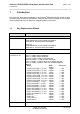
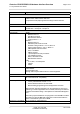
Cinterion® PDS5-E/PDS5-US Hardware Interface Overview Page 9 of 37 1.1 Key Features at a Glance Feature Implementation HSPA features 3GPP Release 6, 7 DL 7.2Mbps, UL 5.7Mbps HSDPA Cat.8 / HSUPA Cat.6 data rates Compressed mode (CM) supported according to 3GPP TS25.
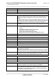
Cinterion® PDS5-E/PDS5-US Hardware Interface Overview Page 10 of 37 1.1 Key Features at a Glance Feature Implementation SIM Application Toolkit SAT Release 99 Firmware update Generic update from host application over ASC0 or USB modem. Interfaces Module interface Surface mount device with solderable connection pads (SMT application interface). Land grid array (LGA) technology ensures high solder joint reliability and provides the possibility to use an optional module mounting socket.
Cinterion® PDS5-E/PDS5-US Hardware Interface Overview Page 11 of 37 1.2 PDS5-E/PDS5-US System Overview 1.
Cinterion® PDS5-E/PDS5-US Hardware Interface Overview Page 12 of 37 2 Interface Characteristics 2 Interface Characteristics PDS5-E/PDS5-US is equipped with an SMT application interface that connects to the external application. The SMT application interface incorporates the various application interfaces as well as the RF antenna interface. 2.1 Application Interface 2.1.1 USB Interface PDS5-E/PDS5-US supports a USB 2.
Cinterion® PDS5-E/PDS5-US Hardware Interface Overview Page 13 of 37 2.1 Application Interface 2.1.2 Serial Interface ASC0 PDS5-E/PDS5-US offers an 8-wire unbalanced, asynchronous modem interface ASC0 conforming to ITU-T V.24 protocol DCE signalling. The electrical characteristics do not comply with ITU-T V.28. The significant levels are 0V (for low data bit or active state) and 1.8V (for high data bit or inactive state). PDS5-E/PDS5-US is designed for use as a DCE.
Cinterion® PDS5-E/PDS5-US Hardware Interface Overview Page 14 of 37 2.1 Application Interface 2.1.3 UICC/SIM/USIM Interface PDS5-E/PDS5-US has an integrated UICC/SIM/USIM interface compatible with the 3GPP 31.102 and ETSI 102 221. This is wired to the host interface in order to be connected to an external SIM card holder. Five pads on the SMT application interface are reserved for the SIM interface. The UICC/SIM/USIM interface supports 3V and 1.8V SIM cards.
Cinterion® PDS5-E/PDS5-US Hardware Interface Overview Page 15 of 37 2.1 Application Interface The figure below shows a circuit to connect an external SIM card holder. V180 CCIN CCVCC SIM 220nF 1nF CCRST CCIO CCCLK Figure 4: External UICC/SIM/USIM card holder circuit The total cable length between the SMT application interface pads on PDS5-E/PDS5-US and the pads of the external SIM card holder must not exceed 100mm in order to meet the specifications of 3GPP TS 51.
Cinterion® PDS5-E/PDS5-US Hardware Interface Overview Page 16 of 37 2.1 Application Interface 2.1.4 Digital Audio Interface PDS5-E/PDS5-US‘s digital audio interface (DAI) can be used to connect audio devices capable of pulse code modulation (PCM). 2.1.5 GPIO Interface PDS5-E/PDS5-US offers a GPIO interface with 8 GPIO lines. The GPIO lines are shared with other interfaces or functions: Fast shutdown (see Section 2.1.11.4), the PWM functionality (see Section 2.1.9), an pulse counter (see Section 2.1.
Cinterion® PDS5-E/PDS5-US Hardware Interface Overview Page 17 of 37 2.1 Application Interface 2.1.6 I2C Interface I2C is a serial, 8-bit oriented data transfer bus for bit rates up to 400kbps in Fast mode. It consists of two lines, the serial data line I2CDAT and the serial clock line I2CCLK. The module acts as a single master device, e.g. the clock I2CCLK is driven by the module. I2CDAT is a bi-directional line.
Cinterion® PDS5-E/PDS5-US Hardware Interface Overview Page 18 of 37 2.1 Application Interface 2.1.8 Analog-to-Digital Converter (ADC) ADC1_IN is used for general purpose voltage measurements. ADC1_IN can be configured and read by AT command - see [1]. 2.1.9 PWM Interfaces The GPIO6 and GPIO7 interface lines can be configured as Pulse Width Modulation (PWM) interface lines PWM1 and PWM2. The PWM interface lines can be used, for example, to connect buzzers.
Cinterion® PDS5-E/PDS5-US Hardware Interface Overview Page 19 of 37 2.2 RF Antenna Interface 2.2 RF Antenna Interface The RF interface has an impedance of 50. PDS5-E/PDS5-US is capable of sustaining a total mismatch at the antenna line without any damage, even when transmitting at maximum RF power. The external antenna must be matched properly to achieve best performance regarding radiated power, modulation accuracy and harmonic suppression.
Cinterion® PDS5-E/PDS5-US Hardware Interface Overview Page 20 of 37 3 Operating Characteristics 3 Operating Characteristics 3.1 Operating Modes The table below briefly summarizes the various operating modes referred to throughout the document. Table 4: Overview of operating modes Mode Function GSM / Normal operation GPRS / UMTS / HSPA SLEEP No call is in progress and the USB connection is suspended by host (or is not present) and no active communication via ASC0.
Cinterion® PDS5-E/PDS5-US Hardware Interface Overview Page 21 of 37 3.2 Power Supply 3.2 Power Supply PDS5-E/PDS5-US needs to be connected to a power supply at the SMT application interface - 6 lines BATT+, and GND. There are two separate voltage domains for BATT+: • BATT+BB with a line for the general power management. • BATT+RF with a line for the GSM power amplifier supply. Please note that throughout the document BATT+ refers to both voltage domains and power supply lines - BATT+BB and BATT+RF.
Cinterion® PDS5-E/PDS5-US Hardware Interface Overview Page 22 of 37 4 Mechanical Dimensions, Mounting and Packaging 4 Mechanical Dimensions, Mounting and Packaging 4.1 Mechanical Dimensions of PDS5-E/PDS5-US Figure 5 shows a 3D view1 of PDS5-E/PDS5-US and provides an overview of the board's mechanical dimensions. For further details see Figure 6. Length: 33mm Width: 29mm Height: 2mm Top view Bottom view Figure 5: PDS5-E/PDS5-US – top and bottom view 1.
Cinterion® PDS5-E/PDS5-US Hardware Interface Overview Page 23 of 37 4.1 Mechanical Dimensions of PDS5-E/PDS5-US Position marker Internal use; Not to be soldered Figure 6: Dimensions of PDS5-E/PDS5-US (all dimensions in mm) PDS5_HIO_v02.
Cinterion® PDS5-E/PDS5-US Hardware Interface Overview Page 24 of 37 5 Regulatory and Type Approval Information 5 Regulatory and Type Approval Information 5.1 Directives and Standards PDS5-E/PDS5-US is designed to comply with the directives and standards listed below.
Cinterion® PDS5-E/PDS5-US Hardware Interface Overview Page 25 of 37 5.1 Directives and Standards Table 7: Standards of European type approval1 ETSI EN 301 489-01 V1.9.2 Electromagnetic Compatibility and Radio spectrum Matters (ERM); Electromagnetic Compatibility (EMC) standard for radio equipment and services; Part 1: Common Technical Requirements ETSI EN 301 489-07 V1.3.
Cinterion® PDS5-E/PDS5-US Hardware Interface Overview Page 26 of 37 5.1 Directives and Standards Table 9: Standards of the Ministry of Information Industry of the People’s Republic of China SJ/T 11363-2006 “Requirements for Concentration Limits for Certain Hazardous Substances in Electronic Information Products” (2006-06). SJ/T 11364-2006 “Marking for Control of Pollution Caused by Electronic Information Products” (2006-06).
Cinterion® PDS5-E/PDS5-US Hardware Interface Overview Page 27 of 37 5.2 SAR requirements specific to portable mobiles 5.2 SAR requirements specific to portable mobiles Mobile phones, PDAs or other portable transmitters and receivers incorporating a GSM module must be in accordance with the guidelines for human exposure to radio frequency energy.
Cinterion® PDS5-E/PDS5-US Hardware Interface Overview Page 28 of 37 5.3 Reference Equipment for Type Approval 5.
Cinterion® PDS5-E/PDS5-US Hardware Interface Overview Page 29 of 37 5.4 Compliance with FCC and IC Rules and Regulations 5.4 Compliance with FCC and IC Rules and Regulations The Equipment Authorization Certification for the Gemalto M2M reference application described in Section 5.
Cinterion® PDS5-E/PDS5-US Hardware Interface Overview Page 30 of 37 5.4 Compliance with FCC and IC Rules and Regulations 1) this device may not cause interference, and 2) this device must accept any interference, including interference that may cause undesired op eration of the device. Le présent appareil est conforme aux CNR d'Industrie Canada applicables aux appareils radio e xempts de licence.
Cinterion® PDS5-E/PDS5-US Hardware Interface Overview Page 31 of 37 6 Document Information 6 Document Information 6.1 Revision History New document: "Cinterion® PDS5-E/PDS5-US Hardware Interface Overview" Version 01.000 Chapter What is new -- Initial document setup. 6.2 [1] [2] [3] [4] Related Documents PDS5-E/PDS5-US AT Command Set PDS5-E/PDS5-US Release Note Application Note 48: SMT Module Integration Universal Serial Bus Specification Revision 2.0, April 27, 2000 6.
Cinterion® PDS5-E/PDS5-US Hardware Interface Overview Page 32 of 37 6.3 Terms and Abbreviations Abbreviation Description dBm0 Digital level, 3.14dBm0 corresponds to full scale, see ITU G.711, A-law DCE Data Communication Equipment (typically modems, e.g.
Cinterion® PDS5-E/PDS5-US Hardware Interface Overview Page 33 of 37 6.
Cinterion® PDS5-E/PDS5-US Hardware Interface Overview Page 34 of 37 6.3 Terms and Abbreviations Abbreviation Description SRAM Static Random Access Memory TA Terminal adapter (e.g.
Cinterion® PDS5-E/PDS5-US Hardware Interface Overview Page 35 of 37 6.4 Safety Precaution Notes 6.4 Safety Precaution Notes The following safety precautions must be observed during all phases of the operation, usage, service or repair of any cellular terminal or mobile incorporating PDS5-E/PDS5-US. Manufacturers of the cellular terminal are advised to convey the following safety information to users and operating personnel and to incorporate these guidelines into all manuals supplied with the product.
Cinterion® PDS5-E/PDS5-US Hardware Interface Overview Page 36 of 37 7 Appendix 7 Appendix 7.
Cinterion® PDS5-E/PDS5-US Hardware Interface Overview Page 37 of 37 7.1 List of Parts and Accessories Table 12: Molex sales contacts (subject to change) Molex For further information please click: http://www.molex.com Molex Deutschland GmbH Otto-Hahn-Str. 1b 69190 Walldorf Germany Phone: +49-6227-3091-0 Fax: +49-6227-3091-8100 Email: mxgermany@molex.com American Headquarters Lisle, Illinois 60532 U.S.A.
35 About Gemalto Gemalto (Euronext NL0000400653 GTO) is the world leader in digital security with 2011 annual revenues of €2 billion and more than 10,000 employees operating out of 74 offices and 14 Research & Development centers, located in 43 countries. We are at the heart of the rapidly evolving digital society. Billions of people worldwide increasingly want the freedom to communicate, travel, shop, bank, entertain and work - anytime, everywhere - in ways that are enjoyable and safe.