User's Manual
Table Of Contents
- Document history
- Introduction
- Product concept
- Application Interface
- Antenna interface
- Electrical, reliability and radio characteristics
- Mechanics
- Reference Approval
- Design example
- List of parts and accessories

MC55/56 Hardware Interface Description
Confidential / Preliminary
s
MC55/56_hd_v03.00 Page 64 of 104 16.08.2005
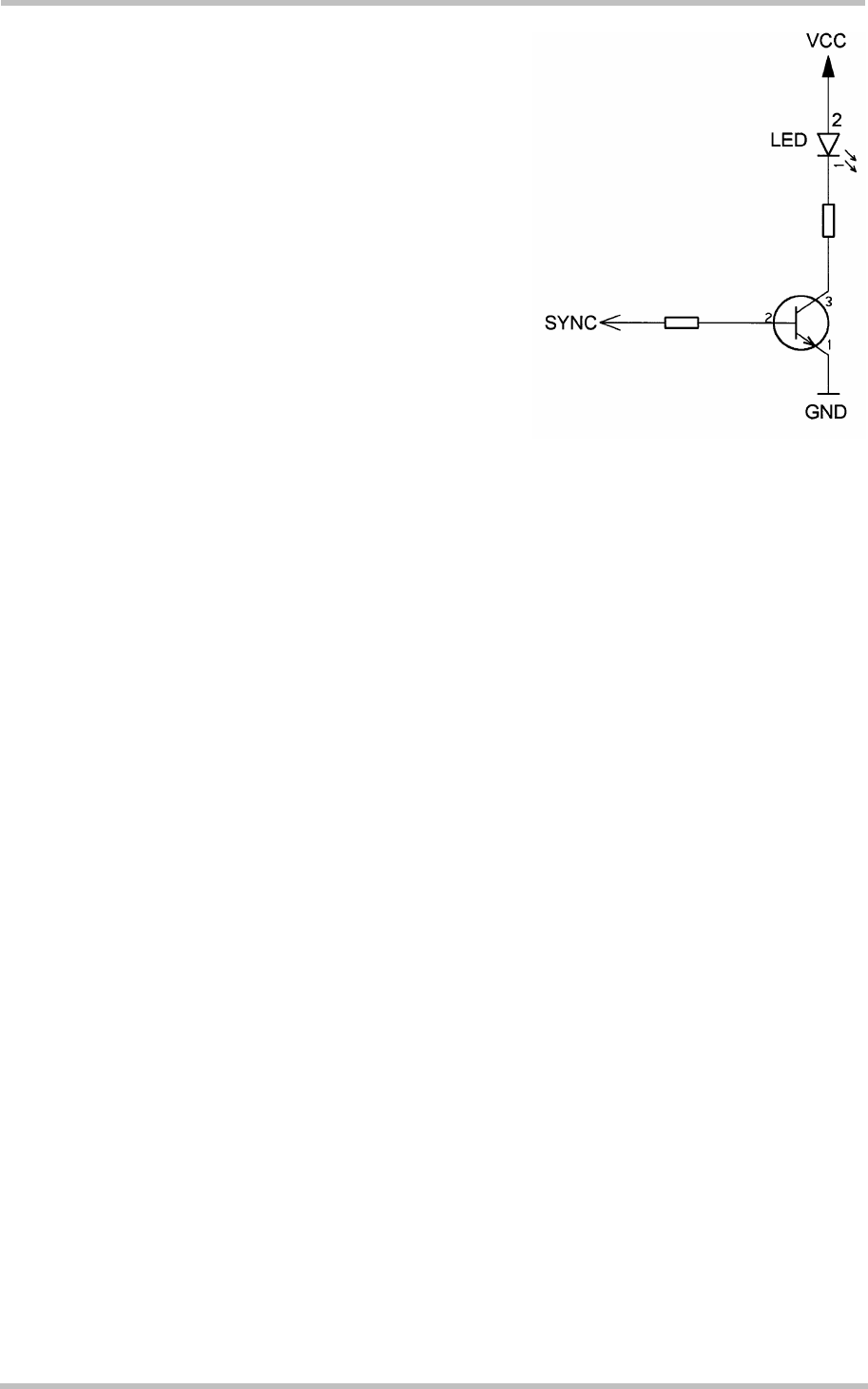
To operate the LED a buffer, e.g. a transistor or gate,
must be included in your application. A sample
configuration can be gathered from Figure 23. Power
consumption in the LED mode is the same as for the
synchronization signal mode. For details see Table 26,
SYNC pin.
Figure 23: LED Circuit (Example)


