User's Manual
Table Of Contents
- Document history
- Introduction
- Product concept
- Application Interface
- Antenna interface
- Electrical, reliability and radio characteristics
- Mechanics
- Reference Approval
- Design example
- List of parts and accessories

MC55/56 Hardware Interface Description
Confidential / Preliminary
s
MC55/56_hd_v03.00 Page 50 of 104 16.08.2005
3.8 RTC backup
The internal Real Time Clock of MC55/56 is supplied from a separate voltage regulator in the
power supply ASIC which is also active when MC55/56 is in POWER DOWN status. An
alarm function is provided that allows to wake up MC55/56 without logging on to the GSM
network.
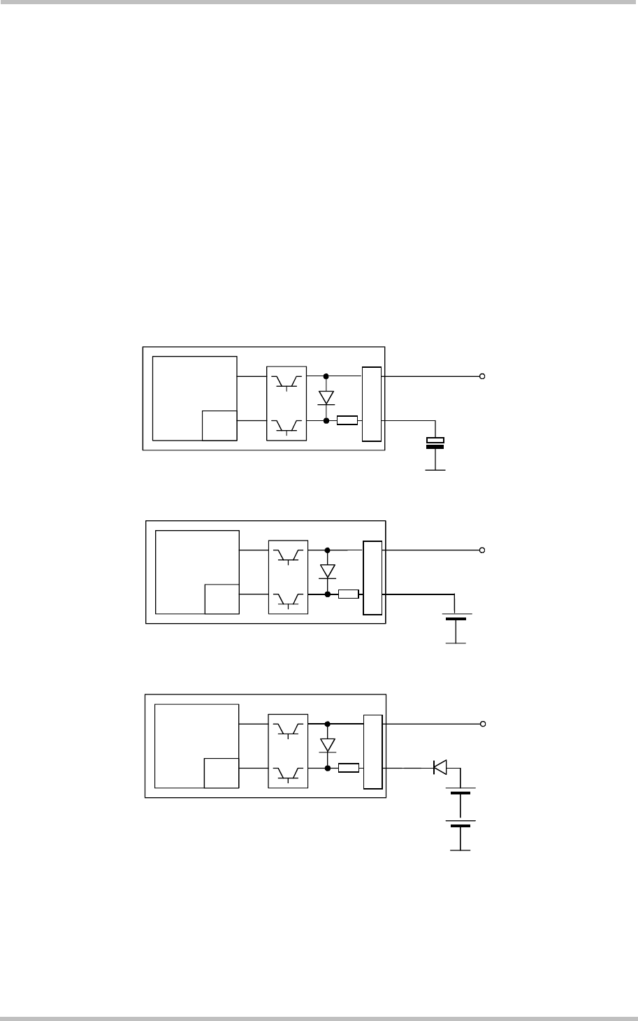
In addition, you can use the VDDLP pin on the board-to-board connector to backup the RTC
from an external capacitor or a battery (rechargeable or non-chargeable). The capacitor is
charged by the BATT+ line of MC55/56. If the voltage supply at BATT+ is disconnected the
RTC can be powered by the capacitor. The size of the capacitor determines the duration of
buffering when no voltage is applied to MC55/56, i.e. the greater capacitor the longer
MC55/56 will save the date and time.
The following figures show various sample configurations. The voltage applied at VDDLP can
be in the range from 2 to 5.5V. Please refer to Table 26 for the parameters required.
Baseband
processor
RTC
PSU
+
BATT+
1k
B2B
VDDLP
Figure 12: RTC supply from capacitor
RTC
PSU
+
BATT+
1k
B2B
VDDLP
Baseband
processor
Figure 13: RTC supply from rechargeable battery
RTC
PSU
+
+
BATT+
1k
VDDLP
B2B
Baseband
processor
Figure 14: RTC supply from non-chargeable battery


