MC55i-W Version: DocId: 01.301 MC55i-W_HIO_v01.
MC55-W Hardware Interface Overview 2 Document Name: MC55-W Hardware Interface Overview Version: 01.301 Date: 2011-3-8 DocId: MC55i-W_HIO_v01.301 Status Confidential / Released Supported Products: MC55i-W GENERAL NOTE THE USE OF THE PRODUCT INCLUDING THE SOFTWARE AND DOCUMENTATION (THE "PRODUCT") IS SUBJECT TO THE RELEASE NOTE PROVIDED TOGETHER WITH PRODUCT. IN ANY EVENT THE PROVISIONS OF THE RELEASE NOTE SHALL PREVAIL. THIS DOCUMENT CONTAINS INFORMATION ON CINTERION PRODUCTS.
MC55i-W Hardware Interface Overview Contents 30 Contents 1 Introduction ................................................................................................................. 6 1.1 Related documents ............................................................................................ 6 1.2 Terms and Abbreviations ................................................................................... 7 1.3 Regulatory and Type Approval Information ...........................................
MC55i-W Hardware Interface Overview Tables 92 Tables Table 1: Table 2: Table 3: Table 4: Table 5: Table 6: Table 7: Table 8: Table 9: Table 10: Table 11: Table 12: Table 13: Table 14: Table 15: Table 16: Table 17: Directives ....................................................................................................... Standards of North American type approval .................................................. Standards of European type approval..................................................
MC55i-W Hardware Interface Overview Figures 92 Figures Figure 1: Figure 2: Figure 3: Figure 4: Figure 5: Figure 6: Pin assignment .............................................................................................. MC55i-W – top view ....................................................................................... Hirose DF12C receptacle on MC55i-W.......................................................... Header Hirose DF12 series.........................................................
MC55i-W Hardware Interface Overview 1 Introduction 14 1 Introduction This document1 describes the hardware of the MC55i-W module that connects to the cellular device application and the air interface. It helps you quickly retrieve interface specifications, electrical and mechanical details and information on the requirements to be considered for integrating further components. 1.
MC55i-W Hardware Interface Overview 1.2 Terms and Abbreviations 14 1.2 Terms and Abbreviations Abbreviation Description ADC Analog-to-Digital Converter AFC Automatic Frequency Control AGC Automatic Gain Control ANSI American National Standards Institute ARFCN Absolute Radio Frequency Channel Number ARP Antenna Reference Point ASC0 / ASC1 Asynchronous Serial Controller.
MC55i-W Hardware Interface Overview 1.2 Terms and Abbreviations 14 Abbreviation Description EMC Electromagnetic Compatibility ESD Electrostatic Discharge ETS European Telecommunication Standard FCC Federal Communications Commission (U.S.
MC55i-W Hardware Interface Overview 1.
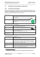
MC55i-W Hardware Interface Overview 1.3 Regulatory and Type Approval Information 14 1.3 Regulatory and Type Approval Information 1.3.1 Directives and Standards MC55i-W has been designed to comply with the directives and standards listed below.
MC55i-W Hardware Interface Overview 1.3 Regulatory and Type Approval Information 14 Table 3: Standards of European type approval ETSI EN 301 489-7 V1.3.
MC55i-W Hardware Interface Overview 1.3 Regulatory and Type Approval Information 14 Table 6: Toxic or hazardous substances or elements with defined concentration limits MC55i-W_HIO_v01.
MC55i-W Hardware Interface Overview 1.3 Regulatory and Type Approval Information 14 1.3.2 SAR Requirements Specific to Portable Mobiles Mobile phones, PDAs or other portable transmitters and receivers incorporating a GSM module must be in accordance with the guidelines for human exposure to radio frequency energy. This requires the Specific Absorption Rate (SAR) of portable MC55i-W based applications to be evaluated and approved for compliance with national and/or international regulations.
MC55i-W Hardware Interface Overview 1.3 Regulatory and Type Approval Information 14 1.3.3 Safety Precautions The following safety precautions must be observed during all phases of the operation, usage, service or repair of any cellular terminal or mobile incorporating MC55i-W. Manufacturers of the cellular terminal are advised to convey the following safety information to users and operating personnel and to incorporate these guidelines into all manuals supplied with the product.
MC55i-W Hardware Interface Overview 2 Product Concept 16 2 Product Concept 2.1 MC55i-W Key Features at a Glance Feature Implementation General Frequency bands Quad band: GSM 850/900/1800/1900MHz GSM class Small MS Output power (according to Release 99, V5) Class 4 (+33dBm ±2dB) for EGSM850 Class 4 (+33dBm ±2dB) for EGSM900 Class 1 (+30dBm ±2dB) for GSM1800 Class 1 (+30dBm ±2dB) for GSM1900 Power supply 3.3V < VBATT+ < 4.
MC55i-W Hardware Interface Overview 2.1 MC55i-W Key Features at a Glance 16 Feature Implementation Software AT commands Hayes 3GPP TS 27.007, TS 27.005, Cinterion Wireless Modules AT commands for RIL compatibility SIM Application Toolkit Supports SAT class 3, GSM 11.
MC55i-W Hardware Interface Overview 3 Application Interface 18 3 Application Interface MC55i-W is equipped with a 50-pin board-to-board connector that connects to the external application. The host interface incorporates several sub-interfaces: power supply, SIM interface, serial interface ASC0, serial interface ASC1, analog audio interface, and DAI/PCM interface (for details see Chapter 2 and Section 5.5). MC55i-W_HIO_v01.
MC55i-W Hardware Interface Overview 3.1 Operating Modes 18 3.1 Operating Modes The table below briefly summarizes the various operating modes referred to in the following sections. Table 7: Overview of operating modes Mode Function Normal operation GSM / GPRS SLEEP Various powersave modes set with AT+CFUN command. Software is active to minimum extent. If the module was registered to the GSM network in IDLE mode, it is registered and paging with the BTS in SLEEP mode, too.
MC55i-W Hardware Interface Overview 4 Antenna Interface 19 4 Antenna Interface The RF interface has an impedance of 50. MC55i-W is capable of sustaining a total mismatch at the antenna connector or pad without any damage, even when transmitting at maximum RF power. The external antenna must be matched properly to achieve best performance regarding radiated power, DC-power consumption and harmonic suppression.
MC55i-W Hardware Interface Overview 5 Electrical, Reliability and Radio Characteristics 25 5 Electrical, Reliability and Radio Characteristics 5.1 Absolute Maximum Ratings Absolute maximum ratings for supply voltage and voltages on digital and analog pins of MC55iW are listed in Table 9. Exceeding these values will cause permanent damage to MC55i-W. Table 9: Absolute maximum ratings Parameter Min Max Unit Supply voltage BATT+ -0.3 +6.0 V Voltage at digital pins in normal operation -0.
MC55i-W Hardware Interface Overview 5.2 Operating Temperatures 25 5.2 Operating Temperatures Please note that the module’s lifetime, i.e., the MTTF (mean time to failure) may be reduced, if operated outside the restriced temperature range. A special URC reports whether the module enters or leaves the restriced temperature range (see [1]; AT^SCTM).
MC55i-W Hardware Interface Overview 5.3 Storage Conditions 25 5.3 Storage Conditions The conditions stated below are only valid for modules in their original packed state in weather protected, non-temperature-controlled storage locations. Normal storage time under these conditions is 12 months maximum. Table 13: Storage conditions Type Condition Unit Reference Air temperature: Low High -40 +85 °C ETS 300 019-2-1: T1.2, IEC 60068-2-1 Ab ETS 300 019-2-1: T1.
MC55i-W Hardware Interface Overview 5.4 Reliability Characteristics 25 5.4 Reliability Characteristics The test conditions stated below are an extract of the complete test specifications. Table 14: Summary of reliability test conditions Type of test Conditions Standard Vibration Frequency range: 10-20 Hz; acceleration: 3.
MC55i-W Hardware Interface Overview 5.5 Electrical Specifications of the Application Interface 25 5.5 Electrical Specifications of the Application Interface The Hirose DF12C board-to-board connector on MC55i-W is a 50-pin double-row receptacle. The names and the positions of the pins can be seen from Figure 2 which shows the top view of MC55i-W.
MC55i-W Hardware Interface Overview 5.6 Power Supply Ratings 25 5.6 Power Supply Ratings Table 15: Power supply ratings BATT+ Description Conditions Min Typ Max Unit Supply voltage Directly measured at module. Voltage must stay within the min/ max values, including voltage drop, ripple and spikes. 3.3 4.0 4.
MC55i-W Hardware Interface Overview 6 Mechanics 28 6 Mechanics The following sections describe the mechanical dimensions of MC55i-W and give recommendations for integrating MC55i-W into the host application. 6.1 Mechanical Dimensions of MC55i-W Figure 2 shows the top view on MC55i-W and provides an overview of the mechanical dimensions of the board. Length: Width: Height: 35mm 32.5mm 3.1mm (including board-to-board connector), 2.
MC55i-W Hardware Interface Overview 6.2 Board-to-Board Connector 28 6.2 Board-to-Board Connector This section provides specifications for the 50-pin board-to-board connector which serves as physical interface to the host application. The receptacle assembled on the MC55i-W PCB is type Hirose DF12C. Mating headers from Hirose are available in different stacking heights.
MC55i-W Hardware Interface Overview 6.2 Board-to-Board Connector 28 6.2.1 Mechanical Dimensions of the Hirose DF12 Connector Figure 5: Mechanical dimensions of Hirose DF12 connector MC55i-W_HIO_v01.
MC55i-W Hardware Interface Overview 7 Reference Approval 30 7 Reference Approval 7.
MC55i-W Hardware Interface Overview 7.2 Compliance with FCC Rules and Regulations 30 7.2 Compliance with FCC Rules and Regulations The Equipment Authorization Certification for the Cinterion Wireless Modules reference application described in Section 7.