User's Manual
Table Of Contents
- Document history
- Introduction
- Product concept
- Application Interface
- Antenna interface
- Electrical, reliability and radio characteristics
- Mechanics
- Reference Approval
- Design example
- List of parts and accessories

MC55/56 Hardware Interface Description
Confidential / Preliminary
s
MC55/56_hd_v03.00 Page 102 of 104 16.08.2005
1nF
200nF
GSM antenna
BATT+
*)
2.2uF
BATT+
Li-Ion
battery pack
Charger
100R
NTC
*)
*)
100nF
10k
3k3
SI3441DV
4V3
1SS355
CRS04
0R
not mounted
BC847
33pF
5.5V - 8V
500mA
LDO
33pF
6R8
6R8
2x4.7nF
2x47nF
27pF
6R8
6R8
2x47nF
470k
3V
3V
22µF
2.2k
2.7k
470k
BC
847
TP1
1M
BC
847
470k
3V
BAV99
10pF
100nF
100nF
2k
100nF
TP2
47k
47k
BC847
3V
3V
100k
100k
GPI
33pF
2.2µF
3V
100nF
47k
TP3
Headset plug in
Push to talk
ESD
BLM 18HG 601
BLM 18HG 601
4x BLM 18HG 601
2x BLM 18HG 601
ESD
ESD
ESD
ESD protection e.g.
1/5 ESDA6V1-5W6
Phone
jack
internal
internal
If internal
transducers
are placed on
PCB ferrite
beads are not
necessary
>100µF
TP0
+
Backup
of RTC
47pF27pF
RXD0
TXD0
GSM
Module
IGT
GND
MICP1MICN1
CTS0
RTS0
DSR0
RING0
VDD
Note:
EMERG
OFF
DTR0
DCD0
RXD0, CTS0, DSR0,
DCD0, RING0
can float if module
is in POWER DOWN state.
Use pull down resistors
(>100k) if necessary.
CCVCC
CCIO
CCCLK
CCRST
CCIN
CCGND
POWER
CHARGE
MICP2
MICN2
EPP1
EPP2
EPN2
BATT_TEMP
VDDLP
EPN1
GPI
GND
TXD
RXD
RTS
CTS
RESET
µC
V+
INT
GPI
GPO
GPO
DSR
DTR
DCD
Oscillator
Keypad
LCD
RESET
SIM
GPI
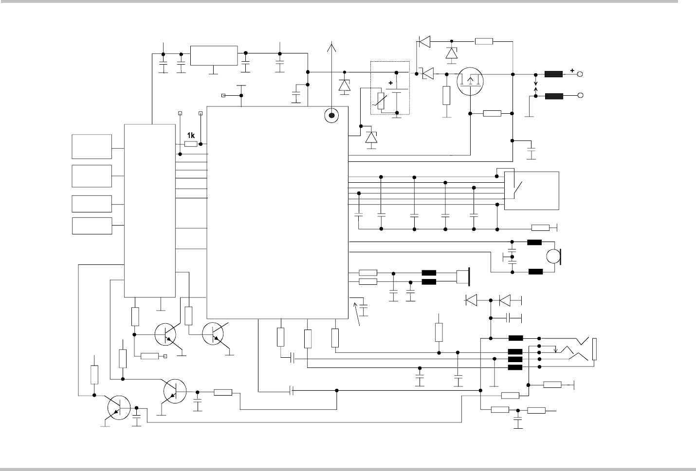
Figure 45: Schematic diagram of MC55/56 sample application


